Table of Contents
Advertisement
Quick Links
Advertisement
Table of Contents

Related Manuals for Cabletron Systems SEHI-22FL


Summary of Contents for Cabletron Systems SEHI-22FL
- Page 1 SEHI-22FL INTELLIGENT STACKABLE HUB USER’S GUIDE...
- Page 2 NOTICE Cabletron Systems reserves the right to make changes in specifications and other information contained in this document without prior notice. The reader should in all cases consult Cabletron Systems to determine whether any such changes have been made. The hardware, firmware, or software described in this manual is subject to change without notice.
-
Page 3: Fcc Notice
Notice FCC NOTICE This device complies with Part 15 of the FCC rules. Operation is subject to the following two conditions: (1) this device may not cause harmful interference, and (2) this device must accept any interference received, including interference that may cause undesired operation. NOTE: This equipment has been tested and found to comply with the limits for a Class A digital device, pursuant to Part 15 of the FCC rules. - Page 4 IMPORTANT: Before utilizing this product, carefully read this License Agreement. This document is an agreement between you, the end user, and Cabletron Systems, Inc. (“Cabletron”) that sets forth your rights and obligations with respect to the Cabletron software program (the “Program”) contained in this package.
-
Page 5: United States Government Restricted Rights
Government is subject to restrictions as set forth in subparagraph (c) (1) (ii) of the Rights in Technical Data and Computer Software clause at 252.227-7013. Cabletron Systems, Inc., 35 Industrial Way, Rochester, New Hampshire 03867-0505. SEHI User’s Guide... -
Page 6: Table Of Contents
CHAPTER 1 INTRODUCTION Using This Manual... 1-1 Document Conventions ... 1-2 Getting Help... 1-3 Related Manuals... 1-3 CHAPTER 2 SEHI FEATURES AND OPTIONS SEHI Overview ... 2-2 SEHI Features ... 2-2 Stackable Capabilities ... 2-3 Remote Network Management Capabilities ... 2-3 Optional Features ... - Page 7 FInishing the Installation ...5-12 CHAPTER 6 TROUBLESHOOTING Installation CheckOut ...6-1 Using LANVIEW...6-2 Using the RESET Button ...6-4 Setting the NVRAM Switch ...6-5 CHAPTER 7 LOCAL MANAGEMENT Local Management Keyboard Conventions ...7-2 Management Terminal Setup...7-3 Accessing Local Management ...7-6 The Feature Selection Screen ...7-7 The Community Name Table Screen...7-8...
- Page 8 APPENDIX A EPIM INFORMATION EPIM Specifications...A-1 A.1.1 EPIM-T ...A-1 A.1.2 EPIM-F1 and EPIM-F2 ...A-2 A.1.3 EPIM-F3 ...A-3 A.1.4 EPIM-C...A-4 A.1.5 EPIM-A and EPIM-X (AUI Port) ...A-5 APPENDIX B IMAGE FILE DOWNLOAD USING OIDs Setting up a UNIX Workstation as a TFTP Server ...B-2 Standard TFTP Download ...B-3 INDEX SEHI User’s Guide...
-
Page 9: Chapter 1 Introduction
Welcome to the Cabletron Systems SEHI-22FL Intelligent Stackable Hub User’s Guide. This manual provides installation instructions and reference information for the SEHI-22FL. The term SEHI (Stackable Ethernet Hub with Intelligence) is NOTE used throughout this manual when describing the features and functions of the SEHI-22FL. -
Page 10: Document Conventions
Management screens and the available commands. Appendix A, EPIM Information, provides specifications, cabling information, and switch settings for the Ethernet Port Interface Modules. Appendix B, Image File Download Using OIDs, provides instructions for setting up a TFTP server and downloading image files to the SEHI by setting specific MIB OID strings. -
Page 11: 1.3 Getting Help
• Network load and frame size at the time of trouble (if known) • The serial and revision numbers of all Cabletron Systems products in the network • The device history (i.e., have you returned the device before, is this a recurring problem, etc.) -
Page 12: Chapter 2 Sehi Features And Options
SEHI FEATURES AND OPTIONS This chapter provides an overview of the SEHI-22FL and contains sections detailing features and available options. The term SEHI (Stackable Ethernet Hub with Intelligence) is NOTE used throughout this manual when describing features and functions of the SEHI-22FL. -
Page 13: Sehi Overview
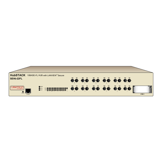
Chapter 2: SEHI Features and Options SEHI OVERVIEW The SEHI-22FL is an intelligent repeating hub providing front panel ports for network connections and a rear panel HubSTACK Interconnect Bus port for stackable connections. The SEHI is designed to manage the Cabletron Systems SEH series of non-intelligent stackable hubs. -
Page 14: Stackable Capabilities
SEHI RJ45 COM port. STACKABLE CAPABILITIES The SEHI intelligent hub is designed to manage the Cabletron Systems series of SEH non-intelligent hubs. The SEHI serves as the logical “top” of the stack. It manages all SEH hubs in the stack providing full packet and error statistics for the entire stack, individual device, or individual port. -
Page 15: Optional Features
The following features are not included with the SEHI, but are purchased separately from Cabletron Systems. Ethernet Port Interface Modules (EPIMs) EPIMs enable the expansion of the network through a variety of media. Cabletron Systems offers the EPIMs shown in Table 2-1. EPIM Media Type EPIM-A... -
Page 16: Chapter 3 Installation Requirements And Specifications
Failure to follow these guidelines can result in poor network performance. CABLE SPECIFICATIONS The SEHI-22FL network ports support 10BASE-FL Multimode Fiber Optic cabling. Ethernet Port Interface Modules (EPIMs) expand a network using Unshielded Twisted Pair (UTP), Shielded Twisted Pair (STP), Multimode Fiber Optic, Single Mode Fiber Optic, or Thin Coaxial cabling. -
Page 17: Hubstack Interconnect Cable Requirements
HubSTACK Interconnect Cable Requirements Attach the SEHI to modules in the stack with the SEHI HubSTACK Interconnect cable available only from Cabletron Systems. Refer to Chapter 1 for cable part numbers. The cable attaches to the SEHI rear panel bus port. -
Page 18: 10Base-T Utp And Stp Cable Specifications
Impedance Cabletron Systems 10BASE-T Twisted Pair products work on twisted pair cable with 75 to 165 ohms impedance. UTP cables typically have an impedance of 85 to 110 ohms. -
Page 19: Network Port Specifications
8 dB to 10 dB/100 meters at 20 C (68 F). The attenuation of PVC insulated cable varies significantly with temperature. At temperatures greater than 40 C (104 F), Cabletron Systems recommends the use of plenum-rated cables to ensure that cable attenuation remains within specification. -
Page 20: Com Port Requirements
COM PORT REQUIREMENTS The RJ45 COM port supports access to a Local Management Console. The Console port supports a Digital Equipment Corporation, VT320 terminal or PC emulation of the VT320 terminal. Figure 3-2 shows the pinouts for the RJ45 COM port. 1. -
Page 21: Operating Specifications
Chapter 3: Installation Requirements and Specifications OPERATING SPECIFICATIONS The operating specifications for the SEHI are described in this section. Cabletron Systems reserves the right to change these specifications at any time without notice. System Specifications Operating System Memory: Internal Processor:... -
Page 22: Power Supply Requirements
Table 3-2. Model Voltage Range 100–125 Vac SEHI-22FL or 200–250 Vac The power supply has two outputs of +5 Vdc and +12 Vdc. The maximum output power is 40 W and the minimum efficiency is 65% under all conditions of the line at full load. -
Page 23: Environmental Requirements
Chapter 3: Installation Requirements and Specifications ENVIRONMENTAL REQUIREMENTS The environmental requirements for the SEHI are detailed in this section. Operating Temperature: Storage Temperature: Operating Humidity: AGENCY APPROVALS The Safety, Immunity, and Emission approvals for the SEHI are detailed in this section. 3.8.1 Safety This unit meets the safety requirements of UL 1950, CSA C22.2 No. -
Page 24: Chapter 4 Installation
3. Visually inspect the SEHI. If there are any signs of damage, contact Cabletron Systems Technical Support immediately. 4. Read the SEHI Release Notes included in the shipping box. Cabletron Systems includes a 3-1/2" disk with the SEHI that NOTE contains a backup copy of the SEHI Flash Firmware Image File. -
Page 25: Pre-Installation Test
DOWN position by looking in through the grillwork on the right side of the hub. If the switch is UP, move it into the DOWN position with a non-metallic tool. Do not remove the chassis cover to perform this operation. -
Page 26: Tabletop Or Shelf Installation
In order to allow for proper cooling, there must be a two-inch clearance on either side and the back of the unit. CAUT ION 18 IN. HubSTACK SEHI-22FL 6 IN. RESET Figure 4-2 Tabletop or Shelf Installation If the installation requires that the SEHI is to be stacked, proceed to Section 4.3.3. -
Page 27: Rackmount Installation
Chapter 4: Installation 4.3.2 Rackmount Installation To install the SEHI in a 19-inch rack, Cabletron Systems offers an accessory kit that includes rackmount brackets, mounting screws, and a strain-relief bracket for cable management. The accessory kit is not included with the SEHI, but can be purchased separately from Cabletron Systems using the part number SEHI-ACCY-KIT. - Page 28 SEHI-ACCY-KIT, attach the rack mounting brackets to each side of the SEHI. HubSTACK 10BASE-FL HUB SEHI-22FL RESET Figure 4-4 Installing the Rack Mounting Brackets 3. Ensure that the rack used will support the unit and that the rack will remain stable with the unit installed in it.
-
Page 29: Stacking The Sehi
Otherwise, continue by connecting power as described in Section 4.4. 4.3.3 Stacking the SEHI The rear panel of the SEHI has an Interconnect Bus Out Port (male connector). Daisy chain units together using Cabletron Systems HubSTACK Interconnect cables. Table 4-1 describes each cable. Table 4-1 HubSTACK Interconnect Cables Part... - Page 30 100BASE-FL HUB WITH LANVIEW® SEH INTERCONNECT SEH-22FL 100BASE-FL HUB WITH LANVIEW® SEH INTERCONNECT SEH-22FL 100BASE-FL HUB WITH LANVIEW® SEH INTERCONNECT SEH-22FL 100BASE-FL HUB WITH LANVIEW® SEH INTERCONNECT SEHI-22FL 100BASE-FL HUB WITH LANVIEW® SEH INTERCONNECT Figure 4-6 Stacking the SEHI Installing the SEHI 165210...
-
Page 31: Connecting The Sehi To The Power Source
After the SEHI runs a self test, the CPU LED blinks green indicating normal operation. If the LED remains red, the processor is faulty, contact Cabletron Systems Technical Support. Disconnect SEH and SEHI Interconnect Cables at the "OUT" Port SEH-22FL 100BASE-FL HUB WITH LANVIEW®... -
Page 32: Adding/Replacing Epims
ADDING/REPLACING EPIMS This section contains procedures on how to add or replace an Ethernet Port Interface Module (EPIM) to upgrade or change the capabilities of your SEHI. After installing a new EPIM, refer to the appropriate EPIM section in Appendix A to verify proper operation. Observe all static precautions while handling EPIMs. -
Page 33: Connecting Network Ports
Connecting an AUI Cable to an EPIM-X 5.1.1 Connecting Network Ports The SEHI-22FL has ST style network ports. Read the following guidelines before connecting a fiber optic link segment to the SEHI: • Insert the connector into the port with the alignment key on the connector inserted into the alignment slot on the port. - Page 34 Label the fiber optic cable to indicate which fiber is receive and which is transmit. Cabletron Systems fiber optic cable is labeled so that one fiber is labeled 1, and the other fiber is labeled 2 at both ends of the cable.
- Page 35 SEHI and the fiber optic device at the other end of the fiber optic link segment. c. Verify that the fiber connection meets the dB loss specifications outlined in Chapter 3. If a link is not established, contact Cabletron Systems Technical Support. SEHI User’s Guide Connecting the SEHI to the Network...
-
Page 36: Connecting A Utp Segment To An Epim-T
If the wires do not cross over, use the switch on the EPIM-T to internally cross over the RJ45 port. Figure 5-2 shows the pin assignment of the port according to the switch position. -
Page 37: Connecting A Fiber Segment To An Epim-F1/F2/F3
If a link is not established, contact Cabletron Systems Technical Support. 5.1.3 Connecting a Fiber Segment to an EPIM-F1/F2/F3 When connecting a fiber optic link segment to an EPIM-F1, F2, or F3 keep the following in mind: • When connecting a fiber optic link segment with SMA 906 connectors to an EPIM-F1 with SMA ports, ensure that the half alignment sleeves (shown in Figure 5-3) are in place on each connector. - Page 38 Verify that the fiber connection meets the dB loss specifications outlined in fiber optic network requirements. If a link is not established, contact Cabletron Systems Technical Support. SEHI User’s Guide...
- Page 39 Connecting the SEHI to the Network F1/F2 ST Connectors F1/F2 SMA 906 Connectors w/ Half Alignment Sleeves SMA 905 Connectors ST Connectors 1490_15 Figure 5-3 The EPIM-F1, EPIM-F2, and EPIM-F3 SEHI User’s Guide...
-
Page 40: Connecting A Thin Coaxial Segment To An Epim-C
5.1.4 Connecting a Thin Coaxial Segment to an EPIM-C To connect a thin coaxial segment to an EPIM-C: 1. Set the Internal Termination Switch, located to the right of the port and labeled TERM to one of the following: •... -
Page 41: Connecting An Aui Cable To An Epim-A
4. Lock the AUI connector into place using the connector slide latch. SEHI User’s Guide Connecting the SEHI to the Network Attach thin coaxial segment directly to BNC connector when internal termination switch is set to On ( ). Figure 5-4 The EPIM-C 1490_16... - Page 42 Chapter 5: Connecting to the Network 5. Check that the PWR LED on the EPIM-A is on. If the LED is not on, contact Cabletron Systems Technical Support. 6. If the PWR LED is on with the AUI cable disconnected, continue with the following checks: a.
-
Page 43: Connecting An Aui Cable To An Epim-X
1. Check that the SQE LED on the EPIM-X is off. If the SQE LED is on, check the position of the SQE switch. If the SQE light remains on, even though the SQE switch is in NOTE the OFF position, contact Cabletron Systems Technical Support. -
Page 44: Finishing The Installation
Chapter 5: Connecting to the Network FINISHING THE INSTALLATION The SEHI is now ready for operation. Before placing the network into service, test the installation thoroughly, making sure that all stations can be addressed and that the SEHI and all stations are indicating normal operation. -
Page 45: Chapter 6 Troubleshooting
This chapter contains instructions for using LANVIEW LEDs to troubleshoot physical layer network problems. It also describes how to reset the SEHI and how to reset the NVRAM switch. INSTALLATION CHECKOUT After connecting the SEHI to the network, verify that the packets pass between all Ethernet devices connected to the SEHI and any other devices connected to the network. -
Page 46: Using Lanview
The affected port remains segmented until a good packet is transmitted/received without collisions. If the LNK LED is still off, contact Cabletron Systems Technical Support. USING LANVIEW The SEHI incorporates the Cabletron Systems LANVIEW status monitoring and diagnostics system. - Page 47 HubSTACK 10BASE-T HUB SEHI-22FL RESET LED NAME (Power) (Central Processing Unit) (Collision) (Receive) (Link) Flashing indicates an irregular LED pulse. NOTE Blinking indicates a steady LED pulse. When this green LED is on, it indicates that the SEHI is receiving power.
-
Page 48: Using The Reset Button
Chapter 6: Troubleshooting This red LED indicates that a collision has occurred on one of the ports. When a yellow RCV LED flashes, it indicates that the SEHI is receiving data packets from the associated port segment. Each SEHI port has a corresponding RCV LED. -
Page 49: Setting The Nvram Switch
SETTING THE NVRAM SWITCH To prevent the possibility of electrical shock, chassis cover to access the NVRAM switch, and use only a non-metallic The SEHI uses NVRAM (Non-Volatile Random Access Memory) to store user-entered parameters such as IP address and Community Names. To... -
Page 50: Chapter 7 Local Management
LOCAL MANAGEMENT This chapter explains how to set up a management terminal to access the SEHI Local Management. It also explains how to use the Local Management screens and commands. Use Local Management to accomplish the following tasks: • Assign an IP address and subnet mask. •... -
Page 51: Local Management Keyboard Conventions
Chapter 7: Local Management LOCAL MANAGEMENT KEYBOARD CONVENTIONS All key names appear in this manual as capital letters. For example, the enter (return) key appears as ENTER and the space bar appears as SPACE bar. Table 7-1 explains the keyboard conventions used in this manual as well as the key functions. -
Page 52: Management Terminal Setup
Use a console cable to attach the management terminal to the SEHI. The console cable is not included with the SEHI, but can be purchased separately from Cabletron Systems as part number SEHI-ACCY-KIT. The SEHI-ACCY-KIT package provides an RJ45 Cable Kit that includes the following: •... - Page 53 Chapter 7: Local Management Console Cable Configuration Use the RJ45 Cable Kit provided with the SEHI-ACCY-KIT package to attach the management terminal to the SEHI COM port as shown in Figure 7-1. Connect the console cable to the SEHI as follows: 1.
- Page 54 Management Terminal Setup Parameters Table 7-2 lists the setup parameters for the local management terminal. If the terminal is a Digital Equipment Corporation VT320 terminal, press F3 to access the Setup Directory. If the Local Management terminal uses terminal emulation of the VT320, refer to the equipment user manual for setup procedures.
-
Page 55: Accessing Local Management
Cabletron SEHI Revision X.XX.XX Cabletron Systems Incorporated 35 Industrial Way, P .O. Box 5005 Rochester, NH 03867-0505 U.S.A. (603) 332-9400 (c) Copyright Cabletron Systems, Inc. 1993 SEHI F/W Version: X.XX.XX Boot Prom Version: X.XX.XX SEHI Board Version: X.X Figure 7-2 Password Screen 1490_21 SEHI User’s Guide... -
Page 56: The Feature Selection Screen
To exit your Local Management session, use the arrow keys to highlight the EXIT LIM SERVICE command, then press ENTER. SEHI User’s Guide The Feature Selection Screen SEHI LOCAL MANAGEMENT Cabletron Systems Incorporated P .O. Box 5005 Rochester, NH 03867-0505 U.S.A. (603) 332-9400 FEATURE SELECTION COMMUNITY NAME TABLE... -
Page 57: The Community Name Table Screen
Chapter 7: Local Management THE COMMUNITY NAME TABLE SCREEN To access the Community Name Table screen from the Feature Selection screen, use the arrow keys to highlight the Community Name Table option, then press ENTER or F6. The Community Name Table screen shown in Figure 7-4 appears. - Page 58 ACCESS Indicates the access status accorded each community name. Possible conditions are as follows: BASIC-READ READ-ONLY READ-WRITE SUPER-USER Editing the Community Name Field The password used to access Local Management at the Password screen must have Super-User privileges for the edits to take effect. If a password is entered with Basic-Read, Read-Only, or Read-Write privileges, Local Management displays the message “AUTHORIZATION PROHIBITS ACCESS”, and does not include editing capabilities.
-
Page 59: The Configuration Screen
Chapter 7: Local Management The first time a user attempts to exit the screen without saving NOTE the changes, a “NOT SAVED?” message is displayed. The edits are lost if the user exits without saving the changes. 6. To exit the screen, press the appropriate Function key or use the arrow keys to highlight the RETURN command. - Page 60 The Configuration Screen The following sections explain each field on the Configuration screen. The number of the interface corresponding to the channels over which packets with that IP Address pass. On the SEHI, this value is “1.” IP Address Displays the IP address of the SEHI. SubNET Mask Displays the subnet mask for the SEHI.
- Page 61 Chapter 7: Local Management Setting the IP Address Use the following steps to set the IP Address: 1. Use the arrow keys to highlight the IP Address field. 2. Enter the IP address into this field. The format for this entry is XXX.XXX.XXX.XXX, with values for XXX being from 0 to 255.
- Page 62 2. Enter the subnet mask into this field. The format for this entry is XXX.XXX.XXX.XXX with values for XXX being from 0 to 255. 3. Press ENTER. 4. Use the arrow keys to highlight the SAVE option, then press ENTER or F6.
-
Page 63: The Trap Table Screen
Chapter 7: Local Management Exiting the Configuration Screen Use the following steps to exit the Configuration screen and return to the Feature Selection screen: 1. Press the appropriate Function key. To return to the Feature Selection screen, use the arrow keys to highlight the RETURN command. 2. - Page 64 Traps Enables transmission of the traps to the network management station with the associated IP address. IP Address Indicates the IP address of the workstation receiving trap alarms from the SEHI. Configuring the Trap Table Use the following steps to configure the Trap table: 1.
-
Page 65: The Snmp Tools Screen
Chapter 7: Local Management THE SNMP TOOLS SCREEN This section describes how to use the SNMP Tools screen to access Management Information Bases (MIBs). Access to screen options depends on the access status accorded to the user’s community name. This section describes Super-User management capabilities. SNMP Tools allows access to valuable MIB information. -
Page 66: Oid Prepend
OID PREPEND Specifies the number prefix common to all Object Identifiers (OIDs) found in the MIBs – 1.3.6.1 is the default prefix OID. This is a modifiable field. Allows the user to retrieve MIB objects using SNMP protocol. Allows users with Read-Write and Super-User access to change modifiable MIB objects, using SNMP protocol. - Page 67 Chapter 7: Local Management Getting Individual OIDs Use the following steps to “Get” individual OIDs: 1. Highlight GET, using the arrow keys, then press ENTER or F6. “<GET> OID (=|F9)” appears. 2. Use one of the following options to enter the OID: •...
- Page 68 3. Press ENTER. If there is no instance of that OID, the return code will specify “MIB_NO_INSTANCE”, otherwise “DATA TYPE:” appears. 4. Enter the data type for that OID. Possible choices are integer, string, null, OID, IP address, counter, gauge, timeticks, and opaque. 5.
-
Page 69: The Device Statistics Screen
Chapter 7: Local Management Cycling Through OIDs Use the following steps to “Cycle” through OIDs: 1. Use the arrow keys to Highlight CYCLES, then press ENTER. 2. Enter the number of cycles desired to occur after “ENTER CYCLE COUNT:”, then press ENTER. 3. - Page 70 The Device Statistics Screen The following sections describe Device Statistics screen fields: BYTES RECEIVED Displays the number of bytes received. FRAMES RECEIVED Displays the number of frames received. ERRORS RECEIVED Displays the number of errors received. COLLISIONS Displays the number of collisions received. OOW COLLISIONS Displays the number of Out Of Window collisions.
- Page 71 Chapter 7: Local Management PORT ADMIN. STATUS Displays the administrative status of the port selected. The two possible status messages are Enable or Disable. PORT SEG. STATUS Displays the segmentation status of the port selected. The two possible status messages are Segmented or Unsegmented. The SEHI and SEH automatically partition problem segments, and reconnect non-problem segments to the network.
- Page 72 PORT This command lets the user view port statistics for ports 1-26 of the selected module. Selecting the Appropriate Module/Port When the Device Statistics screen first appears, statistics are displayed for Module 1 and Port 1. To view statistics for another module and port, use the Module x or Port x commands at the bottom of the screen.
- Page 73 Chapter 7: Local Management Using the DISABLE PORT Command The DISABLE PORT command lets the user disable the port selected in the PORT command. The user must first use the Port command to select the desired port. To set the DISABLE PORT command: 1.
-
Page 74: A.1 Epim Specifications
EPIM SPECIFICATIONS EPIMs enable the connection of the SEHI to the main network using different media types. Cabletron Systems offers a variety of EPIMs. The following sections explain specifications for each EPIM. A.1.1 EPIM-T The EPIM-T is an RJ45 connector supporting UTP cabling. It has an internal Cabletron Systems TPT-T 10BASE-T Twisted Pair Transceiver. -
Page 75: A.1.2 Epim-F1 And Epim-F2
EPIM-F1 and EPIM-F2 The EPIM-F1 and EPIM-F2 shown in Figure A-2 support Multimode Fiber Optic cabling. Each EPIM has an internal Cabletron Systems FOT-F Fiber Optic Transceiver. The EPIM-F1 is equipped with SMA Connectors and the EPIM-F2 is equipped with ST Connectors. -
Page 76: A.1.3 Epim-F3
EPIM-F3 The EPIM-F3 (Figure A-3) supports Single Mode Fiber Optic cabling. It has an internal Cabletron Systems FOT-F Fiber Optic Transceiver and is equipped with ST Connectors. EPIM-F3 specifications are listed below. Transmitter Power decreases as temperatures rise and increases as temperatures fall. -
Page 77: A.1.4 Epim-C
EPIM-C The EPIM-C supports thin coaxial cabling and is equipped with an internal Cabletron Systems TMS-3 Transceiver. Use the TERM switch on the front of the EPIM-C to set the internal 50-ohm terminator. This eliminates the need to connect the port to a T-connector and terminator. -
Page 78: Epim-A And Epim-X (Aui Port
A.1.5 EPIM-A and EPIM-X (AUI Port) The EPIM-A is a DB15 female connector used to attach segments to an external transceiver. The EPIM-X is equipped with dual internal transceivers. It has a DB15 male connector used to attach segments to an AUI cable. -
Page 79: Image File Download Using Oids
IMAGE FILE DOWNLOAD USING OIDs This appendix provides instructions for setting up a TFTP server and to download an image file to the SEHI by setting specific MIB OID strings. Set the OID strings with the SNMP Tools screen described in Chapter 7, Section 7.8. -
Page 80: Appendix Bimage File Download Using Oids
Appendix B: Image File Download Using OIDs SETTING UP A UNIX WORKSTATION AS A TFTP SERVER Due to variations between UNIX systems and individual configurations, this section provides only GUIDELINES for configuring a UNIX workstation to perform an image file download. The instructions include command examples, where appropriate. -
Page 81: Standard Tftp Download
If you do not have a UNIX unzip utility, access to a PC with PKUNZIP, or a way to FTP the decompressed image to your UNIX workstation, contact Cabletron Systems Technical Support. 6. Store the hex image file in the /tftpboot directory as sehi.hex. - Page 82 Appendix B: Image File Download Using OIDs • Enter the FULL path to the image file in the ctDLTFTPRequest OID, including the name of the image file (e.g., c:/tftpboot/sehi.hex). Table B-1 Standard TFTP Download Procedure Step OID Name ctDLForceOnBoot ctDLCommitRAMToFlash 1.3.6.1.4.1.52.4.1.5.8.1.2.0 integer ctDLTFTPRequestHost ctDLTFTPRequest ctDLInitiateColdBoot...
- Page 83 Numerics 10BASE-FL attenuation 3-2 budget and propagation delay 3-2 cable requirements 3-2 10BASE-T cable length 3-3 crosstalk 3-4 delay 3-3 impedance 3-3 insertion loss 3-3 jitter 3-3 noise 3-4 temperature 3-4 UTP and STP specifications 3-3 AUI cable 5-9, 5-11 Cable specifications 3-1 fiber optic 3-2 UTP and STP 3-3...
- Page 84 EPIM-F1/F2/F3 5-5 EPIM-T 5-4 EPIM-X 5-11 fiber optic segment 5-5 thin coaxial 5-8 Unshielded Twisted Pair 5-4 Network port specifications SEHI-22FL 3-4 NVRAM pre-installation checkout 4-2 setting 6-5 OIDs 7-16 Operating specifications 3-6 Port ENABLE override 7-13 Power supply requirements 3-7...
-
Page 85: Power Supply Cord
POWER SUPPLY CORD The mains cord used with this equipment must be a 2 conductor plus ground type with minimum 0.75 mm square conductors and must incorporate a standard IEC appliance coupler on one end and a mains plug on the other end which is suitable for the use and application of the product and that is approved for use in the country of application.
Need help?
Do you have a question about the SEHI-22FL and is the answer not in the manual?
Questions and answers