Table of Contents
Advertisement
Quick Links
Advertisement
Table of Contents

Related Manuals for Cabletron Systems SEH100TX-22


Summary of Contents for Cabletron Systems SEH100TX-22
- Page 1 SEH100TX-22 100BASE-T STACKABLE HUB USER’S GUIDE ®...
-
Page 3: Fcc Notice
Only qualified personnel should perform installation procedures. Cabletron Systems reserves the right to make changes in specifications and other information contained in this document without prior notice. The reader should in all cases consult Cabletron Systems to determine whether any such changes have been made. -
Page 4: Doc Notice
IMPORTANT: Before utilizing this product, carefully read this License Agreement. This document is an agreement between you, the end user, and Cabletron Systems, Inc. (“Cabletron”) that sets forth your rights and obligations with respect to the Cabletron software program (the “Program”) contained in this package. - Page 5 Government is subject to restrictions as set forth in subparagraph (c) (1) (ii) of the Rights in Technical Data and Computer Software clause at 252.227-7013. Cabletron Systems, Inc., 35 Industrial Way, Rochester, New Hampshire 03867-0505. SEH100TX User’s Guide...
-
Page 6: Declaration Of Conformity
Principal Compliance Engineer ___________________________________ Title Rochester, NH, USA ___________________________________ Location 89/336/EEC 73/23/EEC Cabletron Systems, Inc. 35 Industrial Way PO Box 5005 Rochester, NH 03867 Mr. J. Solari Cabletron Systems Limited Nexus House, Newbury Business Park London Road, Newbury Berkshire RG13 2PZ, England... -
Page 7: Table Of Contents
CHAPTER 1 INTRODUCTION Using This Manual... 1-1 Document Conventions ... 1-2 Getting Help... 1-3 Related Manuals... 1-4 CHAPTER 2 SEH FEATURES AND OPTIONS SEH Overview ... 2-2 SEH Features ... 2-2 Stackable Capabilities ... 2-3 Rack Mounting Capabilities ... 2-3 Optional EPIMs... - Page 8 Stacking SEH Hubs with an SEHI ...4-6 4.4.2 Stacking Unmanaged SEH Hubs Together...4-8 Installing an EPIM ...4-8 CHAPTER 5 CONNECTING TO THE NETWORK Connecting the SEH100TX-22 to the Network ...5-1 5.1.1 Connecting to Network Ports...5-1 5.1.2 Connecting to an EPIM-100TX...5-2 5.1.3 nnecting an EPIM-100FX or EPIM-100FMB ...5-4...
-
Page 9: Chapter 1 Introduction
The terms SEH (Stackable Ethernet Hub) and SEHI (Stackable NOTE Ethernet Hub with Intelligence) are used throughout this manual when referring to the SEH100TX-22 and the SEHI100TX-22, respectively. USING THIS MANUAL Read through this manual to gain an understanding of the features and capabilities of the SEH. -
Page 10: Document Conventions
Chapter 1: Introduction DOCUMENT CONVENTIONS The following conventions are used throughout this document: Note symbol. Calls the reader’s attention to any item of NOTE information that may be of special importance. Tip symbol. Conveys helpful hints concerning procedures or actions. Caution symbol. -
Page 11: Getting Help
• Network load and frame size at the time of trouble (if known) • The serial and revision numbers of all Cabletron Systems products in the network • The device history (i.e., have you returned the device before, is this a recurring problem, etc.) -
Page 12: Related Manuals
Chapter 1: Introduction RELATED MANUALS Use the Cabletron Systems SEHI100TX-22 100BASE-T Intelligent Stackable Hub User’s Guide to supplement the procedures and other technical data provided in this manual. The procedures contained in the SEHI100TX-22 100BASE-T Intelligent Stackable Hub User’s Guide are referenced where appropriate, but not repeated in this manual. -
Page 13: Seh Features And Options
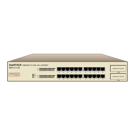
This chapter provides an overview of the SEH (Figure 2-1) and contains sections detailing the features and available options. The abbreviations SEH (Stackable Ethernet Hub) and SEHI NOTE (Stackable Ethernet Hub with Intelligence) are used throughout this manual when referring to the SEH100TX-22 and the SEHI100TX-22, respectively. HubSTACK 100BASE-TX HUB 100TX-... -
Page 14: Chapter 2 Seh Features And Options
Chapter 2: SEH Features and Options SEH OVERVIEW The SEH100TX-22 is a repeating hub providing 22 RJ45 ports and two Ethernet Port Interface Module (EPIM) ports on the front panel for network connections. The SEH has two rear panel Interconnect Bus ports for stackable connections. -
Page 15: Stackable Capabilities
SEH front panel. STACKABLE CAPABILITIES The SEH100TX-22 is a non-intelligent hub designed to be managed by the Cabletron Systems SEHI100TX-22 intelligent hub. The design of the SEH allows the stacking of five SEH hubs in an unmanaged configuration or up to four Cabletron Systems SEH non-intelligent hubs with one SEHI. -
Page 16: Optional Epims
EPIMs are not included with the SEH, but they can be purchased separately from Cabletron Systems. EPIMs enable the expansion of a network through different types of media. Cabletron Systems offers three optional EPIMs for the SEH100TX-22 and SEHI100TX-22 as shown in Table 2-1 Table 2-1 100BASE-TX/FX/FMB EPIMs... -
Page 17: Chapter 3 Installation Requirements And Specifications
Connect units in the stack together with the HubSTACK Interconnect cables shipped with the SEH module and available only from Cabletron Systems (P/N 9380209). The cables attach to the SEH100TX-22 rear panel bus ports. The rear panel of the SEH has an Interconnect Bus Out port and an Interconnect Bus In port to stack hubs together. -
Page 18: Utp Cable Specifications
Chapter 3: Installation Requirements and Specifications 3.1.2 UTP Cable Specifications The device at the other end of the twisted pair segment must meet IEEE 802.3u 100BASE-T specifications. When connecting a 100BASE-TX twisted pair segment to the SEH twisted pair network ports and the EPIM-100TX module, the network must meet the following requirements: Length... -
Page 19: Multimode Fiber Optic Cable Specifications
3.1.3 Multimode Fiber Optic Cable Specifications The SEH supports the Cabletron Systems EPIM-100FX and EPIM-100FMB. These EPIMs meet IEEE 802.3u standards. When connecting a fiber optic segment to the SEH EPIM-100FX or EPIM-100FMB module, the network must meet the following... -
Page 20: Network Cable Lengths
Figure 3-1, is UTP and segment B is fiber optic, the maximum length of the network is 500 meters. If both segments are fiber optic, the maximum length is 800 meters. SEH100TX-22 Figure 3-1 Class I Network SEH100TX User’s Guide... -
Page 21: Network Port Specifications
Table 3-1 summarizes the maximum segment lengths for the type and combination of cables used with a Class I repeater. The maximum length of an individual UTP segment may be no more than 100 meters for proper operation. CAUTION Table 3-1 Maximum Class I Network Cable Length Number Repeaters 200 m... -
Page 22: Operating Specifications
Chapter 3: Installation Requirements and Specifications OPERATING SPECIFICATIONS This section details power supply and environmental requirements. 3.4.1 Power Supply Requirements The SEH has a universal power supply. The input power requirements are listed in Table 3-2. Table 3-2 Power Requirements Line Input Range 100–125 Vac 200–250 Vac... -
Page 23: Immunity
3.5.3 Immunity This unit meets the requirements of EN 50082-1 including IEC 801-2 (ESD), IEC 801-3 (Radiated Susceptibility), and IEC 801-4 (EFT/B). PHYSICAL SPECIFICATIONS This section details the physical specifications for the SEH. Dimensions (H x W x D): Weight: SEH100TX User’s Guide Physical Specifications 2.8 in x 17.0 in x 13.5 in... - Page 24 Chapter 3: Installation Requirements and Specifications SEH100TX User’s Guide...
-
Page 25: Chapter 4 Installation
2. Carefully remove the SEH from the shipping box and set it aside to prevent damage. 3. Visually inspect the SEH. If there are any signs of damage, contact Cabletron Systems Technical Support immediately. Refer to Section 1.3, Getting Help, for instructions. SEH100TX User’s Guide... -
Page 26: Tabletop Or Shelf Installation
Chapter 4: Installation The SEH may be installed on a tabletop or shelf, or in a 19-inch rack, and configured as a standalone or stacked hub. Go to Section 4.2 to install an SEH on a table or shelf. Go to Section 4.3 to install the SEH in a rack. -
Page 27: Rackmount Installation
RACKMOUNT INSTALLATION To install the SEH in a 19-inch rack, Cabletron Systems provides an accessory kit with the SEH that includes rack mounting brackets, mounting screws, and a strain-relief bracket for cable management. Rack mounting the SEH involves the following: •... - Page 28 Chapter 4: Installation Rack Mounting the SEH Refer to Figure 4-3 and proceed as follows to install the SEH into a 19-inch rack. 1. Remove the four cover screws (two from each side) located along the front edges of each side of the SEH. Do not remove the cover from the SEH.
-
Page 29: Powering Up And Stacking The Seh
HubSTACK 100BASE-TX HUB 100TX- Figure 4-4 Installing the SEH in the Rack Proceed to Section 4.4, Powering Up and Stacking the SEH. POWERING UP AND STACKING THE SEH The following section details the procedures that must be followed to power up and interconnect stacked hubs. Failure to follow this procedure may result in damage to the equipment. -
Page 30: Stacking Seh Hubs With An Sehi
Chapter 4: Installation 4.4.1 Stacking SEH Hubs with an SEHI Follow the procedures in this section if you are using an SEHI to manage an SEH stack: The SEH and the SEHI have universal power supplies that NOTE allow connection to power sources from 100 Vac to 125 Vac @ 4.0 A or 200 Vac to 250 Vac @ 2.0 A, 50/60 Hz. - Page 31 5. Attach the interconnect cable to the “IN” port on the rear panel of the SEH as shown in Figure 4-5. REAR VIEW SEHI Managing 4 SEH Non-Intelligent Hubs 100BASE-TX HUB WITH LANVIEW® 100TX 100BASE-TX HUB WITH LANVIEW® 100TX 100BASE-TX HUB WITH LANVIEW® 100TX 100BASE-TX HUB WITH LANVIEW®...
-
Page 32: Stacking Unmanaged Seh Hubs Together
This section contains procedures on how to replace an EPIM-100TX, EPIM-100FX, or EPIM-100FMB to upgrade or change the capabilities of your SEH100TX-22. After installing a new EPIM, refer to the appropriate EPIM section in Appendix A to verify proper operation. - Page 33 To install an EPIM-100TX, EPIM-100FX, or EPIM-100FMB, proceed as follows: When removing an EPIM, pull the module straight out to prevent damage to the connector. CAUTION 1. Remove the coverplate or the existing EPIM (whichever applies). 2. Slide the new EPIM into place, making sure that the connectors on the rear of the EPIM align correctly and firmly with the connector inside the SEH.
- Page 34 Chapter 4: Installation 4-10 SEH100TX User’s Guide...
-
Page 35: Chapter 5 Connecting To The Network
Ensure that the network meets the guidelines and requirements outlined in Chapter 3, Installation Requirements and Specifications, before installing the SEH100TX-22. CONNECTING THE SEH100TX-22 TO THE NETWORK The procedure for connecting network segments to the SEH varies depending on the media and ports being connected. Refer to the following... -
Page 36: Connecting To An Epim-100Tx
Check the cable for continuity. d. Check that the twisted pair connection meets the cable specifications outlined in Section 3.1.2. If a link is not established, contact Cabletron Systems Technical Support. Refer to Section 1.3 for details on getting help. 5.1.2... - Page 37 If the wires do not cross over, use the switch on the EPIM-100TX to internally cross over the RJ45 port. Refer to Figure 5-2 to set the EPIM-100TX crossover switch.
-
Page 38: Nnecting An Epim-100Fx Or Epim-100Fmb
Check that the twisted pair connection meets the cable specifications outlined in Section 3.1.2. e. Check that the crossover switch is in the correct position. If a link is not established, contact Cabletron Systems Technical Support. 5.1.3 nnecting an EPIM-100FX or EPIM-100FMB The EPIM-100FX and EPIM-100FMB have an SC style network port (see Figure 5-3). -
Page 39: Testing The Installation
Verify that the fiber optic connection meets the dB loss specifications outlined in Section 3.1.3. If a link is not established, contact Cabletron Systems Technical Support. Refer to Section 1.3 for instructions on getting help. TESTING THE INSTALLATION The SEH100TX-22 is now ready for operation. - Page 40 Chapter 5: Connecting to the Network SEH100TX User’s Guide...
-
Page 41: Chapter 6 Troubleshooting
TROUBLESHOOTING This chapter contains instructions for using LANVIEW LEDs to troubleshoot physical layer network problems. INSTALLATION TEST After connecting the SEH to the network, verify that packets pass between all Ethernet devices connected to the SEH and any other devices connected to the network. -
Page 42: Using Lanview
The affected port remains segmented until a good packet is transmitted/received without collisions. If the LNK LED is still off, contact Cabletron Systems Technical Support. USING LANVIEW The SEH incorporates the Cabletron Systems LANVIEW status monitoring and diagnostics system. - Page 43 HubSTACK 100BASE-TX HUB 100TX LED NAME (Power) MGMT (Management) (Collision) (Receive) (Link) Flashing indicates an irregular LED pulse. NOTE Blinking indicates a steady LED pulse. When this green LED is on, it indicates that the SEH is receiving power. If this LED is off, it indicates a loss of input power. Check that the power cord is properly plugged into the SEH and into the ac input power source (circuit breaker, fuse, etc.).
- Page 44 Chapter 6: Troubleshooting MGMT This LED flashes when an intelligent hub is managing the SEH. If this LED is not flashing, an intelligent hub is not managing the SEH. If an intelligent hub is attached to the SEH and the LED is not flashing, inspect the HubSTACK interconnect cables for proper connection.
-
Page 45: A.1 Epim Specifications
The slide switch on the EPIM-100TX determines the crossover status of the cable pairs. If the switch is on the X side, the pairs are internally crossed over. If the switch is on the = side, the pairs are not internally crossed over. -
Page 46: A.1.2 Epim-100Fx
Appendix A: EPIM Information A.1.2 EPIM-100FX The EPIM-100FX shown in Figure A-2 supports Multimode Fiber Optic cabling. The EPIM-100FX is equipped with an SC style connector. Specifications for the EPIM-100FX are listed in Table A-1. 1510_10 Table A-1 Transmitter Power (EPIM-100FX) Cable Type 50/125 m fiber optic 62.5/125 m fiber optic... -
Page 47: A.1.3 Epim-100Fmb
The maximum 100BASE-T collision domain using UTP cable to the desktop and fiber cable in the next domain or switch port is only 263 meters (100 meters of UTP and 163 meters of fiber optics). There are circumstances where the maximum fiber optic cable length of 163 meters... - Page 48 Appendix A: EPIM Information Table A-2 provides the specifications for the EPIM-100FMB. Table A-2 Transmitter Power (EPIM-100FMB) Cable Type 50/125 m fiber optic 62.5/125 m fiber optic 100/140 m fiber optic The transmitter power levels and receive sensitivity levels listed are peak power levels after optical overshoot.
- Page 49 6-1 unpacking 4-1 Interconnecting SEHs requirements for 3-1 LANVIEW LEDs 6-3 use of 6-2 Network connection EPIM-100FMB 5-4 EPIM-100FX 5-4 EPIM-100TX 5-2 SEH100TX-22 5-1 Network connection, UTP segments 5-1 Network port specifications SEH100TX-22 3-5 Power supply requirements 3-6 Index-1...
- Page 50 Index Safety, agency approval 3-6 SEH features 2-2 SEH100TX-22 connection of 5-1 Size dimensions 3-7 Specifications environmental requirements 3-6 power supply requirements 3-6 SEH network ports 3-5 Testing 5-5 Troubleshooting 6-1 specification of 3-1 UTP segments connection of 5-1 Index-2...
-
Page 51: Power Supply Cord
The mains cord used with this equipment must be a 2 conductor plus ground type with minimum 0.75 mm square conductors and must incorporate a standard IEC appliance coupler on one end and a mains plug on the other end which is suitable for the use and application of the product and that is approved for use in the country of application.
Need help?
Do you have a question about the SEH100TX-22 and is the answer not in the manual?
Questions and answers