Table of Contents
Advertisement
Quick Links
Advertisement
Table of Contents

Subscribe to Our Youtube Channel
Related Manuals for Sonel S-50 DC


Summary of Contents for Sonel S-50 DC
- Page 3 USER MANUAL HIGH VOLTAGE INSULATION TESTERS S-50 DC ● S-80 DC ● S-110 DC ● S-120 DC SONEL S.A. Wokulskiego 11 58-100 Świdnica Version 1.02 11.09.2020...
- Page 4 S-50 / 80 / 110 / 120 DC is a modern, easy in use and safe testing device. Please acquaint yourself with this manual in order to avoid measuring errors and prevent possible problems in operation of the tester. S-50 DC ● S-80 DC ● S-110 DC ● S-120 DC – USER MANUAL...
-
Page 5: Table Of Contents
6 Technical specifications ................17 7 Accessories ....................19 7.1 Standard accessories ..................... 19 7.2 Optional accessories ....................19 8 Manufacturer ....................19 9 Laboratory services ..................20 S-50 DC ● S-80 DC ● S-110 DC ● S-120 DC – USER MANUAL... -
Page 6: Safety
The note indicates special technical requirements to which the user must pay particu- lar attention when using the system. S-50 DC ● S-80 DC ● S-110 DC ● S-120 DC – USER MANUAL... -
Page 7: Overview And Functions
The two units are linked by a five-pole cable which is connected to the back of the operating unit. Fig. 2.1 View of operating unit (left) and high-voltage unit (right) S-50 DC ● S-80 DC ● S-110 DC ● S-120 DC – USER MANUAL... -
Page 8: Functionality
Alternatively connect the tester to a working power supply or dis- charge the device under test with the ground and discharge rod. S-50 DC ● S-80 DC ● S-110 DC ● S-120 DC – USER MANUAL... -
Page 9: Preparation For Use
The high-voltage unit must always be set up in an upright position and secured against accidental contact during operation. S-50 DC ● S-80 DC ● S-110 DC ● S-120 DC – USER MANUAL... -
Page 10: Assembling The Discharge Rod
110 kV for S-110 DC: 15 000 J (3 µF at 100 kV) d) 125 kV for S-120 DC: 18 750 J (2.4 µF at 125 kV) S-50 DC ● S-80 DC ● S-110 DC ● S-120 DC – USER MANUAL... -
Page 11: Attaching The Corona Ring
The ground rod and discharge rod can be attached to the corona ring to discharge and ground the test object safely. Keep the test object grounded during reassembling the test setup. S-50 DC ● S-80 DC ● S-110 DC ● S-120 DC – USER MANUAL... -
Page 12: Connecting The Test Equipment
If the device is powered by Mains Voltage from a grounded Mains socket (the yellow control light lights on), there is no need of additional grounding by the green/yellow protection ground cable. That’s important to avoid ground loops. S-50 DC ● S-80 DC ● S-110 DC ● S-120 DC – USER MANUAL... - Page 13 Fig. 3.4 Connecting the test equipment for insulation testing of a three-core cable with only one common shield (e.g. PILC). Each core must be tested separately, the other two cores must be shorted to ground. S-50 DC ● S-80 DC ● S-110 DC ● S-120 DC – USER MANUAL...
- Page 14 The sheaths of all three cores can be tested at the same time. The cable shields at the other end of the cable must be disconnected from ground too! S-50 DC ● S-80 DC ● S-110 DC ● S-120 DC – USER MANUAL...
-
Page 15: Operating The Device
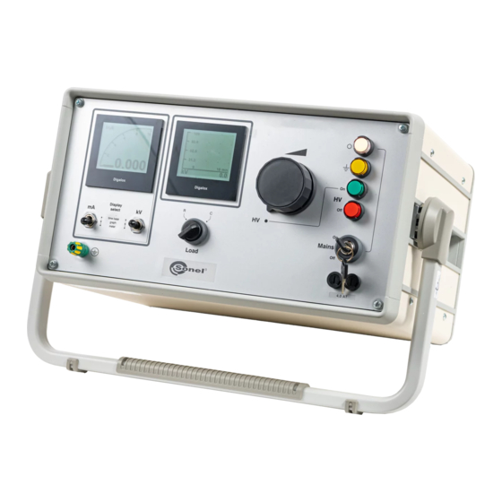
Illuminated button for switching off the high voltage (lights up when the high-voltage is switched on) Mains switch Key-switch Primary fuses "Load" selector switch Switches between resistive and capacitive load S-50 DC ● S-80 DC ● S-110 DC ● S-120 DC – USER MANUAL... -
Page 16: Operating Procedure
The following guide values can be quoted for paper-insulated mass-impregnated cables. Table 4.2 Guide values for leakage currents Leakage current per wire [µA/km] Nominal cable Test voltage [kV] voltage [kV] permitted min. achievable S-50 DC ● S-80 DC ● S-110 DC ● S-120 DC – USER MANUAL... - Page 17 Switching the time base deletes the internal memory of the digital meter. Choose a time base at the beginning of your measurement, which is equal to your expected measure time! S-50 DC ● S-80 DC ● S-110 DC ● S-120 DC – USER MANUAL...
-
Page 18: Ending Testing
WARNING Parallel cables may also still be charged after testing. Always check the oil level (oil level in the centre of the oil-level lens) before testing. S-50 DC ● S-80 DC ● S-110 DC ● S-120 DC – USER MANUAL... -
Page 19: Maintenance And Repair
...................... 0.1 mA / 1 mA / 10 mA ........................0…9.999 mA h) measuring accuracy .................. ±2% (temperature range 23ºC ± 2K) .................. ±1% (temperature range 23ºC ± 2K) ....................±5% (temperature range -25…+55ºC) S-50 DC ● S-80 DC ● S-110 DC ● S-120 DC – USER MANUAL... - Page 20 high-voltage unit at terminals ....................IP00 p) max. voltage / discharge energy for discharge rod S-50 DC ..................50 kV / 7500 J (6 µF at 50 kV) S-80 DC ..................80 kV / 11 250 J (4 µF at 75 kV) ...
-
Page 21: Accessories
+48 74 858 38 60 fax +48 74 858 38 09 E-mail: export@sonel.pl Web page: www.sonel.pl NOTE! Service repairs must be performed only by the manufacturer. S-50 DC ● S-80 DC ● S-110 DC ● S-120 DC – USER MANUAL... -
Page 22: Laboratory Services
Measurements made with an inefficient meter can contribute to an incorrect assessment of the effectiveness of health protection and even human life. S-50 DC ● S-80 DC ● S-110 DC ● S-120 DC – USER MANUAL...
Need help?
Do you have a question about the S-50 DC and is the answer not in the manual?
Questions and answers