Table of Contents
Advertisement
Quick Links
Advertisement
Table of Contents

Related Manuals for Sonel PAT-806-IT


Summary of Contents for Sonel PAT-806-IT
- Page 3 USER MANUAL PORTABLE APPLIANCE TESTER PAT-806-IT SONEL S.A. Wokulskiego 11 58-100 Świdnica, Poland Version 1.07 05.03.2020...
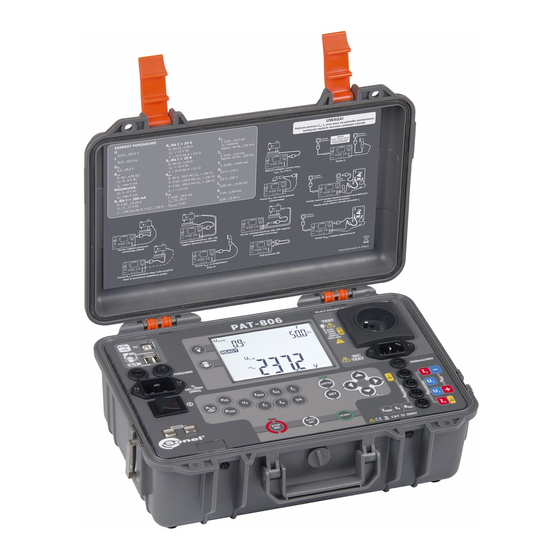
- Page 4 PAT-806-IT meter is a modern, high-quality meter, easy and safe in operation. Please acquaint your- self with the present manual in order to avoid measuring errors and prevent possible problems relat- ed to operation of the meter. PAT-806-IT – USER MANUAL...
-
Page 5: Table Of Contents
5 Memory of measurement result data ............56 5.1 Storing the measurement results in the memory ........... 56 5.2 Viewing memory data ..................... 58 5.3 Deleting memory data .................... 58 5.3.1 Deleting bank data ......................58 PAT-806-IT – USER MANUAL... - Page 6 9 Storage ......................60 10 Dismantling and Disposal ................61 11 Technical specifications ................62 12 Accessories ....................69 12.1 Standard accessories ..................... 69 12.2 Optional accessories ....................69 13 Manufacturer ....................70 14 Laboratory services ..................71 PAT-806-IT – USER MANUAL...
-
Page 7: Safety
PAT-806-IT meter must be operated only by appropriately qualified personnel with relevant certif- icates authorising the personnel to perform works on electric systems. Operating the meter by unauthorised personnel may result in damage to the device and constitute a source of danger for the user. -
Page 8: General Description And Features Of The Instrument
2 General description and features of the instrument PAT-806-IT digital meter is intended to measure the basic parameters of portable electrical de- vices (power tools, household appliances, etc.) important for their safety: protective conductor re- sistance, insulation resistance, continuity of connections, the leakage current. - Page 9 large, readable display with backlight option ergonomic operation Note: The displayed E02 symbol informs that the 10/25 A test set is damaged. The machine must be sent for repair. PAT-806-IT – USER MANUAL...
-
Page 10: Switching On And General Settings
500 mA fuse protects 200 mA current controller for R measurement. 3.2 Changing the type of mains (TN or IT) Connect the device to the target mains. Turn on the device and keep SET button pressed, until the following screen is displayed: PAT-806-IT – USER MANUAL... -
Page 11: Start Test After Switching The Meter On
checking the continuity PE in the power supply socket measuring the voltage between N and PE in the power supply socket When everything is correct the following screen is displayed: PAT-806-IT – USER MANUAL... -
Page 12: General Settings - Menu
updating firmware operating the meter with a bar-code reader and printer transferring data to a pen-drive setting nominal network voltage setting current values in the measurement of R on IEC lead. PAT-806-IT – USER MANUAL... -
Page 13: Setting Date And Time
MENU without changing any set- tings. Notes: - The value or symbol to be changed is blinking. - Exit MENU using STOP/ESC. - Settings are stored in memory after switching off the meter. 3.4.1 Setting date and time PAT-806-IT – USER MANUAL... -
Page 14: Communication With Pc
Press ENTER to confirm the set- tings or ESC, to exit to main MENU without changing any settings. 3.4.2 Communication with PC Press ENTER to start the transmis- sion. PAT-806-IT – USER MANUAL... -
Page 15: Firmware Update
Notes: - New versions of software for the meter are available at www.sonel.pl. - This function may be used only by the computer proficient users. - During programming, do not turn off the power supply of the meter and the power supply should be stable. - Page 16 1. Connect the reader to your PC. 2. Wait until the reader is installed on your system. 3. Point the reader at the following code pressing the button. The reader signals successful read-out by lighting green LED and a beep. PAT-806-IT – USER MANUAL...
-
Page 17: Printer Settings
ESC, to exit to main MENU without changing any settings. Note: - The printer must be connected to any of the USB socket of "Host" type. - Supported types of printers: Brother PT-9700PC, Brother QL-720NW, Brother QL-820NWB. PAT-806-IT – USER MANUAL... -
Page 18: Transferring Data To A Pen-Drive
- Pen-drive must be plugged into the left USB socket of "Host" type. - The content of memory is transferred to the pen-drive as a file in an independent format interpreted by "Sonel Reader" freeware and "Sonel PAT" commercial software. Additional information displayed by the meter No communication or poor communication with the pen- drive. -
Page 19: Setting Nominal Network Voltage
Notes: - Nominal network voltage is used in I function for calculating the leakage current, which is meas- ured at a voltage of 40V and its value is rescaled to the nominal voltage. PAT-806-IT – USER MANUAL... -
Page 20: Setting Current Values In The Measurement Of R
3.4.8 Setting current values in the measurement of R on IEC lead test Press ENTER. to set the test current (10 A or 200 mA). Press ENTER, to confirm the set- tings, or ESC, to exit to main MENU without changing any settings. PAT-806-IT – USER MANUAL... -
Page 21: Configuration Of Settings From Pc
When using "Sonel PAT" software - start to configure the settings by pressing Settings 1 button displayed in the main window (Main functions tab), then in "Software settings" window press Meter settings 2 . - Page 22 When using "Sonel Reader" press Meter configuration PAT80x 1 button: In both programs, window "PAT80x Settings" will be displayed: Window for configuring general settings. You can use this module to enter your contact details which will be visible on the reports printed directly from the meter (using an optional printer).
- Page 23 PAT-806-IT – USER MANUAL...
-
Page 24: Measurements
(limits) including the date and time of measurement. - All data can be entered using the program on your PC. 4.1 Preliminary test Connect the mains plug of the tested device into the test socket of the meter. PAT-806-IT – USER MANUAL... - Page 25 ( is displayed). Symbol indicates the possibility to check the fuse removed from the tested device. Contact the fuse with the test points. The efficiency of the fuse is indicated by displaying and an acoustic signal. PAT-806-IT – USER MANUAL...
-
Page 26: Measurement Of Protective Lead Resistance Using 200 Ma Current
Measurement of protective lead resistance using 200 mA current Keep pressing R button, until the screen in- forming about the readiness for measurement with 200 mA current is displayed. When parameters must be changed press SET. to set the upper limit of R resistance. PAT-806-IT – USER MANUAL... - Page 27 Press ENTER to confirm the settings. Connect the mains plug of the tested device into the test socket of the meter. Use the probe connected to socket I2 and touch metal parts of the tested device connected to PAT-806-IT – USER MANUAL...
- Page 28 STOP/ESC. Correct result: R < LIMIT Incorrect result: R > LIMIT Notes: - Tested device must be turned on. - Test circuit is electrically isolated from the mains and from PE mains lead. PAT-806-IT – USER MANUAL...
-
Page 29: Compensation Of The Test Lead Resistance During The Measurement Of The Protective Lead Resistance Using 200 Ma Current (Auto-Zero)
Completed auto -zero process is signalled during the measurement by displaying In order to remove auto-zero proceed in the same manner, but disconnect the test lead from PE. After finishing, for 1s is displayed message PAT-806-IT – USER MANUAL... -
Page 30: Measurement Of Protective Lead Resistance Using 10/25 A Current
25 A current at short intervals. - The method of measurement and other observations are the same as for the measurement of 200 mA. Additional information displayed by the meter Non-continuity in the test circuit during the measurement PAT-806-IT – USER MANUAL... -
Page 31: Two-Wire Measurement Of Protective Lead Resistance Using 10/25 A Current
10 A or 25 A current (auto-zero) In R 10A or 25A mode, press . Auto-zero screen will appear with blinking symbol Use the probe connected to I2 socket and touch PE pin of the test socket. PAT-806-IT – USER MANUAL... -
Page 32: Three-Wire Measurement Of Protective Lead Resistance Using 10/25 A Current
Use the power probe (or Kelvin crocodile clip) connected to U2 and I2 sockets and touch metal parts of the tested device connected to PE. The method of measurement and observations are the same as for the measurement of 200 mA. PAT-806-IT – USER MANUAL... -
Page 33: Four-Wire Measurement Of Protective Lead Resistance Using 10/25 A Current
U voltage, the lower limit value and measurement time. For the triple meas- urement U voltage is set for all three measure- ments as well as limits and measurement times for each measurement. PAT-806-IT – USER MANUAL... -
Page 34: Iso Measurement On Devices Of Class I
) press and hold START. To block the measurement press ENTER. At the time with pre-set value it is not nec- essary. Signalling the presence of high-voltage View of the screen during measurement. Time remaining to the end of the measurement PAT-806-IT – USER MANUAL... -
Page 35: Riso Measurement On Devices Of Class Ii (Iii)
Connect the mains plug of the tested device into the test socket of the me- ter. L and N are shorted. Use the probe connected to socket R - and touch the conductive accessible parts of the tested device. PAT-806-IT – USER MANUAL... -
Page 36: Iso
LN-PE measurement LN-PE measurement time a limit value for LN-S measurement LN-S measurement time a limit value for PE-S measurement PE-S measurement time, where S means shorted outputs of the welding machine. PAT-806-IT – USER MANUAL... - Page 37 Press START button to start the measure- ments that are executed automatically one after the other. The final measurement result for all resistances above the limit values are shown below. PAT-806-IT – USER MANUAL...
-
Page 38: Measurement Of Substitute Leakage Current
Measurement of substitute leakage current current is measured at 25 V...50 V voltage and its value is rescaled to the nominal mains voltage set in menu (see 3.3.7). Press I . After that meter is prepared for measurement. PAT-806-IT – USER MANUAL... - Page 39 For Class II and for accessible parts not connected to PE in Class I, additionally connect I2 socket to the probe which will be used for touching accessible parts of the tested device. PAT-806-IT – USER MANUAL...
- Page 40 Incorrect result: I > LIMIT Notes: - Tested device must be turned on. - Test circuit is electrically isolated from the mains and from PE mains lead. - Test voltage is 25 V ... 50 V rms PAT-806-IT – USER MANUAL...
-
Page 41: Measurement Of Pe Leakage Current
The measurement is made between shorted L, N and PE. In addition, it is possible to carry out the measurement with the probe connected to R - socket. Settings and the measurement are as in 4.5.1. PAT-806-IT – USER MANUAL... -
Page 42: Measurement Of Differential Leakage Current
Measurement of differential leakage current It is recommended for checking the welding equipment to use the measurements: the leakage current of the primary circuit and leakage current welding circuit. Press I . After that meter is prepared for ∆ measurement. PAT-806-IT – USER MANUAL... - Page 43 - The result of measurement may be affected by the presence of external fields and by the current used by the device. Note: The differential method of leakage current measurement is permitted by EN 60974-4 standard as an alternative for measuring the primary leakage current performed during periodic tests of welding equipment. PAT-806-IT – USER MANUAL...
-
Page 44: Measurement Of Touch Leakage Current
Class I the socket must have PE). Additionally connect the probe which will be used for touching accessible parts of the tested de- vice (for parts of Class I accessible and not connected to PE). Settings and measurements as in section 4.5. PAT-806-IT – USER MANUAL... -
Page 45: Measurement Of Leakage Current In The Primary Circuit Of The Welding Machine Using Pat Ipe Adapter
Following measurement method is recommended to check the welding machines (in accordance with PE-EN 60974-4 standard). The adapter may be used only with PAT-806-IT device to measure the leakage current in the welding machine primary circuit. Any application that differs from those specified in the present manual may result in danger to the user. - Page 46 Depending on the type of power supply provided to the welding machine - apply one of the following diagrams. Unused leads must be plugged into appropriate sockets. Connect the banana socket of the adapter to I2 socket of PAT-806-IT. Power supply from 230 V mains Mains...
- Page 47 The measurement ends after the preset time runs out or after pressing STOP/ESC. After the measurement is completed, read the result. Correct result: I < LIMIT Incorrect result: I > LIMIT Settings and measurements as in section 4.5.1. PAT-806-IT – USER MANUAL...
-
Page 48: Rated Voltage Measurement On Welding Equipment Without Load
When the limit value must be changed press SET. Connect the power plug of the tested welding machine to the mains socket, other than PAT. Connect the outputs of the weld- ing machine to U1 and U2 sockets of the meter. PAT-806-IT – USER MANUAL... - Page 49 200 Ω...5 kΩ, as defined in EN 60974-4. Positive and negative peak values are measured and the highest measured value is displayed. - Tested device must be turned on. - The measuring time is not set. PAT-806-IT – USER MANUAL...
-
Page 50: Leakage Current Measurement On Welding Circuit I
SET (upper limit value and the measurement time are set). Connect the power plug of the tested welding machine to the mains socket, other than PAT. Connect the outputs of the weld- ing machine to U1 and U2 sockets of the meter. PAT-806-IT – USER MANUAL... - Page 51 - The measurement is performed in two stages: I leakage current is measured successively for both welding machine outputs and the higher value is displayed. - Tested device must be turned on. - The measurement is in compliance with EN 60974-4. PAT-806-IT – USER MANUAL...
-
Page 52: Measurement Of Current, Power Consumption And Voltage
Press ENTER, if this test is successful ( is displayed) or STOP/ESC, when the test result is negative ( is dis- played). Notes: During the measurement in the test socket the voltage of mains is present. PAT-806-IT – USER MANUAL... -
Page 53: Iec Lead Test
Connect the mains plug into the test socket and the other into the IEC socket. Press START. The measurement may be stopped before the set time runs out by pressing STOP/ESC. After measuring is completed, read the re- sult: PAT-806-IT – USER MANUAL... -
Page 54: Automatic Tests
- If no test is programmed, after pressing AUTO the meter immediately enters the set-up mode is displayed). - Programmed test is a test where at least for one class, one measurement is performed (set on - Default programmed tests are: 1 ... 4 for all three classes. PAT-806-IT – USER MANUAL... - Page 55 ENTER. to select the device class and confirm by pressing ENTER. Press START to start the measurement. PAT-806-IT – USER MANUAL...
- Page 56 ) or cancel it ( To change the parameters of the active measurement press SET. Set the next pa- rameters as in section 4.2. Confirm by press- ing ENTER. Use to activate and set pa- rameters of the next measurement. PAT-806-IT – USER MANUAL...
- Page 57 - For R measurement, there are three options: - no R measurement, R 1 - R standard measurement, R 3 - R triple measurement - only for welding machines. PAT-806-IT – USER MANUAL...
-
Page 58: Memory Of Measurement Result Data
5 Memory of measurement result data PAT-806-IT meter has memory divided into 10 banks of 99 cells. Each measurement result can be stored in a memory cell marked with a selected number and in a selected memory bank. Thanks to this, the user of the meter can, at his/her option, assign memory cell numbers to individual meas- urement points and the memory bank numbers to individual facilities. - Page 59 Read the bar-code of the tested device, then the meter will record the result and the code in selected memory cell, and it will proceed to the measurement screen. In order to skip reading the barcode press ENTER. PAT-806-IT – USER MANUAL...
-
Page 60: Viewing Memory Data
In the mode of displaying the network voltage press ENTER. 5.3.1 Deleting bank data set the number of a cell on 0. Press SET to select the num- ber of a bank. Use set the bank number to be deleted. PAT-806-IT – USER MANUAL... -
Page 61: Deleting The Whole Memory
Press ENTER, to start deleting or STOP/ESC, to cancel. 5.3.2 Deleting the whole memory set the number of bank at 0. Proceed similarly as when deleting data bank. PAT-806-IT – USER MANUAL... -
Page 62: Report Printing
In order to operate the meter with a PC, an USB cable is required and appropriate software. The kit includes "Sonel Reader" software used for reading data. Increased ability to read data and create reports are provided by "Sonel PAT" software, which can be purchased from the manufacturer or au- thorized distributor. -
Page 63: Dismantling And Disposal
Used electronic equipment should be sent to a collection point in accordance with the Used Elec- trical and Electronic Equipment Act. Before the equipment is sent to a collection point, do not dismantle any elements. Observe the local regulations concerning disposal of packages. PAT-806-IT – USER MANUAL... -
Page 64: Technical Specifications
0.01 Ω 1.00 Ω ... 19.99 Ω (4 % m.v. + 3 digits) Influencing factor Designation Additional uncertainty Position Supply voltage 0.1 %/° C for R ≥ 0.5 Ω Temperature 0 %/ºC for R < 0.5 Ω PAT-806-IT – USER MANUAL... - Page 65 Test range according to IEC 61557-2 for U Display range Resolution Basic uncertainty 0 kΩ...1999 kΩ 1 kΩ (5 % m.v. + 8 digits) 2.00 MΩ ... 19.99 MΩ 0.01 MΩ 20.0 MΩ ... 99.9 MΩ 0.1 MΩ PAT-806-IT – USER MANUAL...
- Page 66 "Cont" mode (continuous measurement) 4 s…3 min with a resolu- tion of 1 s detection of a dangerous voltage before commencing a measurement discharging the object tested Note: For R <50 kΩ, the uncertainty is not specified. PAT-806-IT – USER MANUAL...
- Page 67 0.01 mA ... 9.9 mA 0.01 mA with resolution of 0.01 mA / 0.1 mA adjustable measuring time in the range of: Cont , 4 s…60 s with resolution of 1 s PAT-806-IT – USER MANUAL...
- Page 68 0.01 mA ... 9.9 mA with resolution of 0.01 mA / 0.1 mA adjustable measuring time in the range of: Cont , 4 s…60 s with resolution of 1 s PAT-806-IT – USER MANUAL...
- Page 69 EN 60974-4 adjustable upper limit in the range of: 0.10 mA…14.90 mA with resolution of 0.1 mA adjustable measuring time in the range of: 6 s…60 s with resolution of 1 s PAT-806-IT – USER MANUAL...
- Page 70 During the measurement of PE continuity with PE 10/25 current the meter may pro- duce interference with values exceeding allowable limits defined in EN 61326-1 and cause interference in other devices. Note: F500mA/250V fuse protects the following measurements: R 200mA, I and I PAT-806-IT – USER MANUAL...
-
Page 71: Accessories
Kelvin crocodile clip 1pc – WAKROKELK06 1kV probe - black 1pc – WASONBLOGB3 power probe Sonel 1pc – WASONSPGB1 USB cable – WAPRZUSB fuse 0314 015.VXP 15A 250VAC 6.3x32mm Littlefuse 2 pcs – WAPOZB15PAT ... -
Page 72: Manufacturer
*** - These adapters are designed for testing security of devices powered from industrial sockets 16 A and 32 A, providing that the tested device does not consume current higher than 16 A. The adapters enable users to perform all measurements available in PAT-806-IT meter on the network measure- ment socket. -
Page 73: Laboratory Services
National Metrological Institute. According to ILAC-G24 „Guidelines for determination of calibration intervals of measuring instru- ments”, SONEL S.A. recommends periodical metrological inspection of the instruments it manufac- tures no less frequently than once every 12 months. - Page 74 NOTES PAT-806-IT – USER MANUAL...
Need help?
Do you have a question about the PAT-806-IT and is the answer not in the manual?
Questions and answers