Table of Contents
Advertisement
Quick Links
Advertisement
Table of Contents

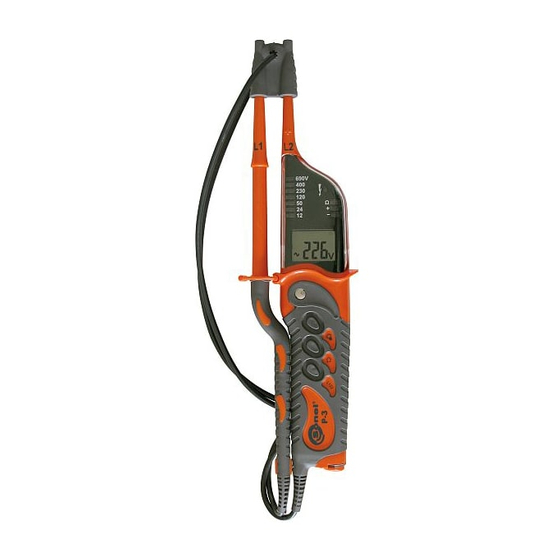
Summary of Contents for Sonel P-3
- Page 3 OPERATING MANUAL VOLTAGE TESTER SONEL S. A. ul. Wokulskiego 11 58-100 Świdnica Version 1.6 May 22, 2012...
-
Page 4: Table Of Contents
TECHNICAL DATA ....... 14 MANUFACTURER ......16 We appreciate your having purchased our voltage tester. The P-3 tester is a modern high- quality, simple and safe device. However it is rec- ommended to get acquainted with the present manual in order to avoid measuring errors and prevent possible problems related to operation of the meter. -
Page 5: Safety
Safety The P-3 meter has been devised for the pur- pose of voltage and circuit continuity testing, measurement of resistance and indication of the phase spin direction and phase identification. In order to guarantee proper operation and adequacy of the results the following recommendations must be observed: •... -
Page 6: Measurements
Note: The device can be used in rainy conditions, however at user’s own responsibility. It is recommended to use gauntlets. Measurements Tester operation control Before each operation of the tester, its func- tioning must be checked: • Test the voltage indicator using a known volt- age source, •... -
Page 7: Rcd Operation Test
Notes: In mains protected with an RCD switch, whose nominal current is 10mA or 30mA, the switch may be activated during a voltage measurement be- tween L and PE. In order to avoid that connect the tester between L and N and after approximately 5s switch the probe over from N to PE. -
Page 8: Circuit Continuity Test
Single-pole phase testing may not be sufficient to determine whether the circuit is live. Perform two-pole voltage test. Circuit continuity test Note! The tested object must not be live. Connect both probes to the tested object. A sound signal, diode Ω on, and the legend in- dicate continuity of the circuit (R<600kΩ). -
Page 9: Phase Sequence Test
Phase sequence test Notes: The phase sequence may solely be deter- mined in a three-phase system. Contact of the touch electrode during measurement in a single- phase system gives a random result. Phasing The phasing function facilitates comparison of voltage phases in two distant point of the installa- tion. -
Page 10: Without Transmitter
2.8.1 Without transmitter... -
Page 11: With Transmitter
P-3 indicator. Repeated mating is re- quired in case another P-3 indicator is to be used. If the transmitter and indicator mating has not been performed, go on to point 2.8.2.1 of the man-... - Page 12 Note : Green light signal indicated operation of the transmitter in the P-3 mode. 3. Press fleetingly the L123 button on the P-3 dis- play. The following message should be displayed and after a short while the symbol 4. Then hold the L123 button until the message is displayed 5.
- Page 13 2.8.2.2 Correct work of the P-3 indicator with the LKN-710P transmitter...
-
Page 14: Lighting Of The Measured Point
10-20 sec- onds. symbol, which appears when the symbol is displayed continuously means: - no voltage at the P-3 indicator measurement ter- minals, - incorrect connection of the LKN-710P transmitter or the P-3 indicator. -
Page 15: Cleaning And Maintenance
Cleaning and maintenance NOTE! Use solely the maintenance techniques speci- fied by the manufacturer in the present operat- ing manual. The tester may be cleaned with a soft, damp cloth using all-purpose detergents. Do not use any solvents or cleaning agents which might scratch the casing (powders, pastes, etc.). -
Page 16: Technical Data
Technical data The abbreviation „i.v.” in the basic uncertainty definition means the indicated value. Constant voltage measurement (on the dis- play): Basic Range Resolution uncertainty +1,5/-2,5* 0,1V ±(2% i.v. + 3 ...49,9V digits) 50...750V * - from 6,0V for Sr. no. up to 681793 Additionally the voltage is indicated by the diode bar for the following values: 12, 24, 50, 120, 230, 400, 690V along with the signalling of the voltage... - Page 17 b) Measurement category: III 1000V (IV 600V) in accordance with EN 61010-1 c) Casing protection grade in accordance with EN 60529: IP65, with an open battery com- partment: IP10 d) Voltage measurement range on the LCD: 6…750V AC/DC e) Voltage indication for the diode bar: 12V, 24V, 50V, 120V, 230V, 400V, 690V Minimum indicator activation voltage: g) Accuracy of voltage indications: in accordance...
-
Page 18: Manufacturer
0,25kg 8 Manufacturer The manufacturer of the device, which also provides guarantee and post-guarantee service is the following company: SONEL S.A. ul. Wokulskiego 11 58-100 Świdnica Poland tel. +48 74 858 38 60 fax +48 74 858 38 09 E-mail: export@sonel.pl...


Need help?
Do you have a question about the P-3 and is the answer not in the manual?
Questions and answers