Table of Contents
Advertisement
Quick Links
Advertisement
Table of Contents

Related Manuals for Sonel P-2


Summary of Contents for Sonel P-2
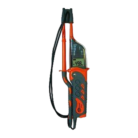
- Page 3 OPERATION MANUAL VOLTAGE TESTER SONEL S. A. ul. Wokulskiego 11 58-100 Świdnica Version 1.8 May 15, 2012...
- Page 4 Principal characteristics of the device: • Measurement of direct and alternative voltage presented on a display within the range between 1.5 and 750V with the maximum exactitude of 0.1V, • Indication of direct and alternative voltage on the diode indicator: 12, 24, 50, 120, 230, 400, 690V, •...
-
Page 5: Table Of Contents
TECHNICAL DATA ....... 10 MANUFACTURER ......12 Thank you for having purchased our voltage tester. The P-2 tester is a modern, high-quality measure- ment instrument, which is easy and safe to use. However, reading the present manual will permit you to avoid measurement errors and prevent possible problems regarding operation of the device. -
Page 6: Safety
Safety The purpose of the P-2 device is to test voltage and the continuity of connections as well as meas- urements of resistance. In order to guarantee the correct operation of the device and correctness of the obtained results observe the following recom- mendations: •... -
Page 7: Measurements
Measurements Control of operation of the tester Before each use of the tester, it is necessary to control its operation: • The voltage indicator must be tested using a known source of voltage, • Close the measurement probes – there should be an audible acoustic signal, the LED Ω... -
Page 8: Rcd Operation Test
ment of voltage between L and PE. In order to avoid that connect the tester between L and N and after approximately five seconds switch the probe from N to PE. RCD operation test In order to check the operation of the RCD switch whose nominal current is 10mA or 30mA it is necessary to realise a voltage test directly between the L phase and the protective cable PE. -
Page 9: Circuit Continuity Test
Circuit continuity test Note! The measured object may be live. Connect both the probes to the measured ob- ject. An acoustic signal, lit Ω diode and the symbol appearing on the display indicate continuity of the circuit (R<600kΩ). Note: During the measure of continuity polarization of the voltage at the L2 probe is negative. -
Page 10: Phase Order Test
Illumination of the measured point The P-2 tester offers the possibility of illumina- tion of the measured area under difficult light condi- tions (e.g. in switchgears). In order to illuminate the measured point press the button marked with the symbol . -
Page 11: Replacement Of The Batteries
Replacement of the batteries The tester is powered by means of two 1.5V AAA batteries. A lack of acoustic signal once both the probes have been closed, too weak illumination after the button has been pressed or the symbol appearing on the display indicate the necessity to replace the batteries. -
Page 12: Dismantling And Utilization
Dismantling and utilization Worn electric and electronic equipment must be disposed of selectively, i.e. it must not be disposed of along with waste of other kinds. Send worn electronic equipment to a collection point in accordance with the act on worn electric and electronic equipment. - Page 13 The frequency of the measurement voltage for the diode indicator: 15…400Hz. Measurement of resistance: Fundamental Range Exactitude uncertainty ±(3% d.v. + 0...1999Ω 1Ω 8 digits) Other data: a) Kind of insulation: double, in accordance with EN 61010-1 b) Measurement category: III 1000V (IV 600V) in accordance with EN 61010-1 c) Protection grade for the casing in accordance with EN 60529: IP65...
-
Page 14: Manufacturer
EN 61326-1:2006 and EN 61326-2-2:2006 8 Manufacturer The manufacturer of the instrument who pro- vides guarantee and post-guarantee service is: SONEL S.A. ul. Wokulskiego 11 58-100 Świdnica Poland tel. +48 74 858 38 60 fax +48 74 858 38 09 E-mail: export@sonel.pl...
Need help?
Do you have a question about the P-2 and is the answer not in the manual?
Questions and answers