
Related Manuals for Met One Instruments AEROCET 532


Summary of Contents for Met One Instruments AEROCET 532
- Page 1 AEROCET 532 ANUAL Met One Instruments, Inc Corporate Sales & Service: 1600 NW Washington Blvd. Grants Pass, OR 97526 Tel (541) 471-7111 Fax (541) 471-7116 www.metone.com service@metone.com...
- Page 2 Copyright Notice AEROCET 532 Manual © Copyright 2021 Met One Instruments, Inc. All Rights Reserved Worldwide. No part of this publication may be reproduced, transmitted, transcribed, stored in a retrieval system, or translated into any other language in any form by any means without the express written permission of Met One Instruments, Inc.
-
Page 3: Table Of Contents
K-Factors ........................... 18 5.3.4. Flow ........................... 19 5.3.5. Display ..........................20 5.3.6. Docking Station ......................... 20 5.4. Initial Setup Screen ......................... 22 5.4.1. Serial ..........................22 5.4.2. Modbus ..........................23 5.4.3. Clock ..........................24 AEROCET 532 Manual Rev B Page 3... - Page 4 8.2. Zero Count Test ........................32 8.3. Flow Rate Test......................... 32 8.4. Annual Calibration ........................33 8.5. Filter Change ........................... 33 8.6. Flash Upgrade ......................... 33 Troubleshooting ....................34 10. Specifications ...................... 35 AEROCET 532 Manual Rev B Page 4...
-
Page 5: Introduction
(AT) / relative humidity (RH) probe. Sample history events can be viewed on the LCD display and downloaded to a computer. An optional Docking Station complements the Aerocet 532. It charges the unit and increases communication options with RS-485, Ethernet, and WiFi. - Page 6 PN 400113 Rubber Boot Carrying Case PN 550537 PN 83549 Figure 1 - Standard Equipment Flow Meter Flow Meter Docking Station PN 9801 PN Swift 6.0 PN 83529 Figure 2 – Optional Accessories AEROCET 532 Manual Rev B Page 6...
-
Page 7: Layout
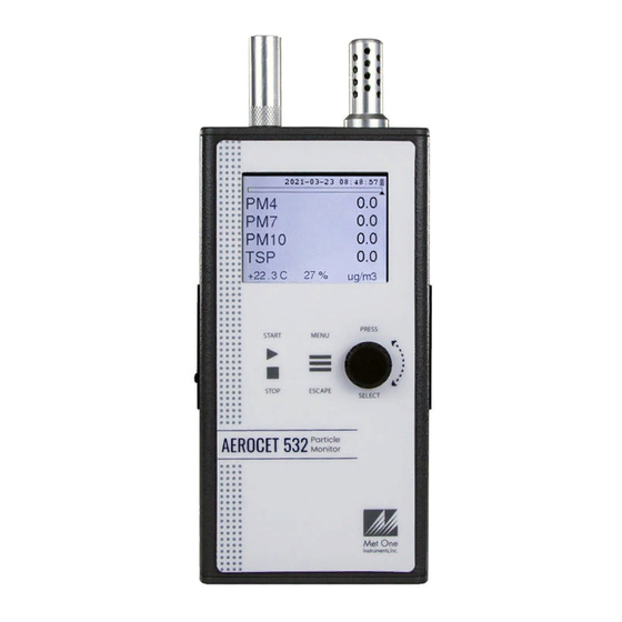
2.2. Layout Figure 3 shows the layout of the AEROCET 532 and provides a description of each of the components. Isokinetic Probe AT/RH Sensor Charging Jack USB C Port Rotary Dial Power Switch Bottom Connection Keypad Figure 3 – AEROCET 532 Layout... -
Page 8: Default Settings
115200 2.4. Initial Operation Before operating the AEROCET 532 for the first time, it is recommended that the unit be fully charged. Information regarding charging the battery is found in section 6 of this manual. Complete the following steps to verify proper operation. -
Page 9: Operation
4.2. Power Up AEROCET 532 power is controlled by a slide switch located on the left hand side of the unit. Move the power switch to the on position (towards the top of the case) to power up the unit. - Page 10 Figure 4 – Mass Operate Screen Figure 5 – Count Operate Screen AEROCET 532 Manual Rev B Page 10...
-
Page 11: Sampling
4.3.2. Sample Status The top of the Operate screen displays the status of the AEROCET 532 while the unit is sampling. The time remaining is shown at the top left of the screen. A status bar fills with green as time progresses. -
Page 12: Sample Related Functions
Start Stop Sample Time Time Time Figure 8 – Manual Mode Sample Start Stop Sample Time Hold Time Sample Time Time Time Figure 9 – Auto Mode Sample AEROCET 532 Manual Rev B Page 12... -
Page 13: Menu Selections
Press to select the item. Rotate the dial to change the the dial setting. Press the dial to save the setting or APE to cancel and return to the previous screen. AEROCET 532 Manual Rev B Page 13... -
Page 14: Sample Setup Screen
PM10 and lower. Conversely, when sampling in count mode, the size selections represent the lower threshold of your sample. An example would be that the 1.0 µm cumulative size contains all particulate that are 1.0 µm and larger. AEROCET 532 Manual Rev B Page 14... -
Page 15: Mode
60 seconds. Hold times greater than 60 seconds will increase pump life, as well as increase operating time because of lower battery usage. This setting will not appear on the Sample Setup screen if Single mode is selected. AEROCET 532 Manual Rev B Page 15... -
Page 16: Toolbox Screen
5.3.1. Units The Units setting allows the volume and temperature units to be selected. Volume: The AEROCET 532 supports total counts per timed sample (TC), particles per liter (/L), particles per cubic foot (CF), and particles per cubic meter (M3). Particle count information updates while the unit is sampling. -
Page 17: Memory
5.3.2. Memory The AEROCET 532 can store up to 15,000 sample records in its memory. For instructions on viewing stored data, see section 4.3.3. Because this memory is circular, once all 15,000 records are full, any new samples taken will overwrite the oldest stored sample data. -
Page 18: K-Factors
Calculate the K-Factor for each particulate size fraction as the reference concentration divided by the AEROCET 532 light scatter concentration over the same time period. For example, if the reference total concentration was 51 μg/m and the AEROCET total concentration was 38 μg/m... -
Page 19: Flow
PWM is in a good place. An orange progress bar indicates the filter is getting close to needing to be replaced. A red progress bar indicates the filter needs to be replaced. Figure 17 - Flow Screen Progress Bar Color Changes AEROCET 532 Manual Rev B Page 19... -
Page 20: Display
IP address changes. The 83529 Docking Station quick setup manual explains how to connect the unit to the optional docking station. Select WiFi Discovery to begin the procedure. Figure 19 - Docking Station Screen AEROCET 532 Manual Rev B Page 20... - Page 21 Press escape to exit this screen. WiFi Configuration WiFi Configuration Uses: DHCP Conn: Your_WiFi Host: Esp-link Timed Out! 192.168.0.28 Mask: 255.0.0.0 10.0.0.1 Figure 21 - WiFi Configuration Results (left) and Time Out Screen (right) AEROCET 532 Manual Rev B Page 21...
-
Page 22: Initial Setup Screen
Figure 22 – Initial Setup Screen 5.4.1. Serial The Serial setting controls the behavior of the AEROCET 532 serial output hardware available on the optional docking station. The following table lists the Serial settings and describes their meanings. -
Page 23: Modbus
WiFi or Ethernet and are selected by a switch on the Docking Station. The equipment Modbus address is also set in this screen with values of 1-247. Figure 24 - Modbus Setup Screen AEROCET 532 Manual Rev B Page 23... -
Page 24: Clock
Press the dial to select each character. All 7 characters must be selected to save the location ID. It is suggested to use spaces for a location with less than 7 characters. Figure 26 - Locations Screen AEROCET 532 Manual Rev B Page 24... -
Page 25: About Screen
Hz. A discharged battery pack will take approximately 2.5 hours to fully charge. When fully charged the battery inside the AEROCET 532 will power the unit for over 8 hours of continuous sampling. For continuous operation, operate the unit with the battery charger attached. -
Page 26: Serial Communications
Serial Communications The AEROCET 532 provides serial communications via the USB connector located on the right hand side of the unit. RS-485, WiFi, and Ethernet communications are also available with the optional 83529 Docking Station. Refer to the 83529 Docking Station Quick Setup Guide to configure the optional communications. - Page 27 Sample Mode. SM 0=Single, SM 1=Continuous Serial Number Sample Time. ST 0=1-min, ST 1=2-min, ST 2=5-min, ST 3=10-min, ST 4=15-min, ST 5=30-min, ST 6=1-hour. Temperature Units. TU 0=C, TU 1=F DISPTO Manual Display Timeout. 0=None, 1=1-min, 2=5-min, 3=10-min. AEROCET 532 Manual Rev B Page 27...
-
Page 28: Comma Separated Value (Csv)
Channel 6 Size 5.0 (TC, /L, CF, M3) 00000353 Channel 7 Size 7.0 (TC, /L, CF, M3) 00000353 Channel 8 Size 10 (TC, /L, CF, M3) +024.9 AT (C, F) RH (%) LOC1 Location 0060 Seconds 0000 Status AEROCET 532 Manual Rev B Page 28... -
Page 29: Mass Format
For example, 18 = IOP Alarm and Temperature Sensor Alarm. Status Bits Value Condition OK (no alarms or errors) Not used IOP Alarm (Laser) Not used Not used Temperature Sensor Alarm Pressure Sensor Alarm AEROCET 532 Manual Rev B Page 29... -
Page 30: Modbus Communication
7.3. MODBUS Communication The Aerocet 532 supports MODBUS communications protocol with any serial connection that is set in the Modbus Setup in Section 5.4.2. The serial transmission is RTU mode. Flow Control must be set to none if using Ethernet. The following MODBUS registers are used to access various readings. -
Page 31: Last Data Record Readings
1558 float Last Sample PM 2.5 PM_4 1560 float Last Sample PM 4 PM_7 1562 float Last Sample PM 7 PM_10 1564 float Last Sample PM 10 PM_TSP 1566 float Last Sample TSP AEROCET 532 Manual Rev B Page 31... -
Page 32: Maintenance
Due to the nature of the instrument, there are minimal customer serviceable components in the AEROCET 532. The case of the AEROCET 532 should never be removed or opened for any reason. Opening or removing the case of the AEROCET 532 voids the warranty and may result in exposure to laser radiation, which can cause eye injury. -
Page 33: Annual Calibration
8.4. Annual Calibration The AEROCET 532 should be sent back to Met One Instruments, Inc. yearly for calibration and inspection. The annual calibration cannot be performed by the customer because this calibration requires specialized equipment and a skilled technician. Met One Instruments, Inc. -
Page 34: Troubleshooting
The AEROCET 532 case should never be removed or opened for any reason. Opening or removing the case will void the warranty and may result in exposure to laser radiation, which can cause eye injury. -
Page 35: Specifications
AC Adapter/Battery Charger Iso-kinetic Sample Probe RH and Temperature Probe Carrying Case Rubber Boot Zero Particulate Filter Optional Ball Flow Meter kit (PN 9801) Digital Flow Meter (PN Swift 6.0) Docking Station (PN 83529) AEROCET 532 Manual Rev B Page 35...
Need help?
Do you have a question about the AEROCET 532 and is the answer not in the manual?
Questions and answers