
Related Manuals for Met One Instruments AEROCET 531S


Summary of Contents for Met One Instruments AEROCET 531S
- Page 1 AEROCET 531S ANUAL Met One Instruments, Inc Corporate Sales & Service: 1600 NW Washington Blvd. Grants Pass, OR 97526 Tel (541) 471-7111 Fax (541) 471-7116 www.metone.com service@metone.com...
- Page 2 Copyright Notice AEROCET 531S Manual © Copyright 2014 Met One Instruments, Inc. All Rights Reserved Worldwide. No part of this publication may be reproduced, transmitted, transcribed, stored in a retrieval system, or translated into any other language in any form by any means without the express written permission of Met One Instruments, Inc.
-
Page 3: Table Of Contents
Sensitivity .......................... 16 5.4. Serial Screen ........................... 17 5.4.1. Report ..........................17 5.4.2. Baud Rate ......................... 17 5.4.3. Serial ..........................17 5.5. Recall Data Screen ........................18 5.6. Print Data Screen ........................18 AEROCET 531S Manual Rev H Page 3... - Page 4 8.2. Zero Count Test ........................30 8.3. Flow Rate Test......................... 30 8.4. Annual Calibration ........................30 8.5. Flash Upgrade ......................... 30 Troubleshooting ....................31 10. Specifications ...................... 32 11. Warranty / Service ....................33 AEROCET 531S Manual Rev H Page 4...
-
Page 5: Introduction
Introduction The AEROCET 531S is a full–featured, battery operated, handheld particle counter or mass monitor. In count mode, the unit will measure particle counts at four fixed sizes (0.5 µm, 1.0 µm, 5.0 µm, and 10.0 µm) when set to low sensitivity and five fixed sizes (0.3 µm, 0.5 µm, 1.0 µm, 5.0 µm, and 10.0 µm) when set to high sensitivity (See Section 5.3.3 for more... - Page 6 ATTENTION: The included USB drivers must be installed before connecting the AEROCET 531S USB port to your computer. If the supplied drivers are not installed first, Windows may install generic drivers that are not compatible with this product. To install USB drivers: Insert the Comet CD.
- Page 7 Carrying Case USB Cable PN 8517 PN 500787 Figure 1 – Standard Accessories T/RH Probe Serial Cable Printer Flow Meter PN G3120 PN 3228 PN G3115 PN 9801 Figure 2 – Optional Accessories AEROCET 531S Manual Rev H Page 7...
-
Page 8: Layout
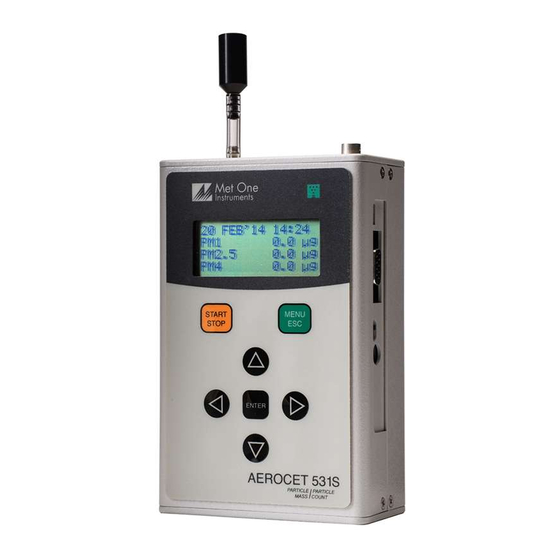
2.2. Layout The following figure shows the layout of the AEROCET 531S and provides a description of each of the components. Inlet Nozzle AT/RH Connector USB Port Serial Port Power Switch Charging Jack Figure 3 – AEROCET 531S Layout Component... -
Page 9: Default Settings
RS-232 2.4. Initial Operation Before operating the AEROCET 531S for the first time, it is recommended that the unit be fully charged. Information regarding charging the battery is found in section 6 of this manual. Complete the following steps to verify proper operation. -
Page 10: Operation
4.3. Power Up AEROCET 531S power is controlled by a slide switch located on the right hand side of the unit. Move the power switch to the on position (towards the top of the case) to power up the unit. -
Page 11: Operate Screen
3 lines scroll to display the full list. AT and RH data will precede the location number when the AT/RH probe is attached. Ambient temperature (AT) can be displayed in units of Celsius (C) or Fahrenheit (F). AEROCET 531S Manual Rev H Page 11... -
Page 12: Sampling
3.5 µg Figure 7 – Operate Screen Sampling 4.4.2. Sample Status The top line of the Operate screen displays the status of the AEROCET 531S while the unit is sampling. The following table shows the various status messages: Status Description AEROCET 531S is starting the sample and is waiting for the STARTING... -
Page 13: Warning / Error Messages
5.2. 4.5.5. Real-Time Serial Report AEROCET 531S provides real-time report out the serial port at the end of each sample. The format of the report is controlled by the REPORT setting (Section 5.4). Section 7.3 covers the real-time output format. -
Page 14: Sample Timing
Adjust the sample flow rate Flow screen SET CLOCK Set the date and time. Set Clock screen SET CONTRAST Adjust the display contrast. Set Contrast screen ABOUT Display firmware version and serial number. About screen AEROCET 531S Manual Rev H Page 14... -
Page 15: Edit Menu Items
0.5 µm, 1.0 µm, 5.0 µm, and 10.0 µm when using COUNTS low sensitivity 0.3 µm, 0.5 µm, 1.0 µm, 5.0 µm, and 10.0 µm when using high sensitivity. AEROCET 531S Manual Rev H Page 15... -
Page 16: Sample Mode
Figure 12 – SETTINGS Screen 5.3.1. Volume The AEROCET 531S supports total counts (TC), particles per liter (/L), particles per cubic foot (CF), and particles per cubic meter (M3). Particle count information updates while the unit is sampling. Concentration values (/L, CF, M3) are time dependent so these values may fluctuate early in the sample;... -
Page 17: Serial Screen
Figure 13 – SERIAL Screen 5.4.1. Report REPORT setting determines the behavior of the AEROCET 531S serial output and report format. The settings are NONE, CSV or PRINTER. The following table lists the REPORT settings and describes their meanings. See section 7 for report examples. -
Page 18: Recall Data Screen
The location ID of the sample events to print. Setting LOCATION location to 000 prints all locations. Settable from 0 – 999. 01 JAN’00 00:00 The date/time to begin printing sample events from. 18 AUG’06 13:23 The date/time to end printing samples. AEROCET 531S Manual Rev H Page 18... -
Page 19: Memory Screen
5.7. Memory Screen The AEROCET 531S memory is composed of a single file which contains the data from sample events. Every time a sample is completed, the AEROCET 531S stores that data into the memory. The AEROCET 531S memory is circular, meaning when the memory is full, the unit will start overwriting the oldest saved samples with new samples. -
Page 20: Set Flow Screen
5.8. Set Flow Screen The AEROCET 531S has a factory calibrated flow rate of 0.1 CFM (2.83 LPM). Use the following procedure to adjust the flow rate when a periodic flow rate check (Section 8.3) indicates a flow rate error greater than +/- 5%. -
Page 21: Set Contrast Screen
To charge the battery, connect the battery charger to an AC power outlet and the DC barrel connector to the socket on the right side of the AEROCET 531S. The battery charger is universal and will work with power line voltages of 100 to 240 volts, 50 to 60 Hz. -
Page 22: Serial Communications
AEROCET 531S. ATTENTION: The included USB drivers must be installed before connecting the AEROCET 531S USB port to your computer. If the supplied drivers are not installed first, Windows may install generic drivers that are not compatible with this product. -
Page 23: Serial Interface
7.1. Serial Interface The serial interface to the AEROCET 531S is a standard 9 pin (DB-9) connector. It is located on the right hand side of the instrument as shown below. Communication with the AEROCET 531S requires a custom serial cable (PN 3228). -
Page 24: Commands
7.2. Commands AEROCET 531S provides serial commands for accessing stored data and settings. All commands are terminated by a carriage return. These commands are not case sensitive. The following table lists the available commands. These commands are available via USB, RS-232 and RS-485 hardware interfaces. The settings (baud rate, parity and stop bits) must match the computer setting for proper communication regardless of the hardware interface type (USB, RS-232 or RS-485). -
Page 25: Real Time Output
The real time output occurs when the unit finishes a sample. The output format is either off (NONE), a comma separated value (CSV) or a printer (PRINTER) depending on the REPORT style settings (see section 5.4.1) AEROCET 531S Manual Rev H Page 25... -
Page 26: Comma Separated Value (Csv)
2. Units determined by product setting. 0.3 will be null (,,) if set to low Not used sensitivity. Not used 3. Temperature and RH will be null (,,) if Temp/RH probe is not attached Low battery AEROCET 531S Manual Rev H Page 26... -
Page 27: Mass Format
4. The sample time is fixed at 60 seconds. Low battery 5. Status bits combinations are possible. See the Status Bits table. Sensor error For example, 48 (00110000B) = Low battery and Sensor error. AEROCET 531S Manual Rev H Page 27... -
Page 28: Printer Format
Due to the nature of the instrument, there are no customer serviceable components in the AEROCET 531S. The case of the AEROCET 531S should never be removed or opened for any reason. Opening or removing the case of the AEROCET 531S voids the warranty and may result in exposure to laser radiation, which can cause eye injury. -
Page 29: Zero Count Test
8.4. Annual Calibration The AEROCET 531S should be sent back to Met One Instruments yearly for calibration and inspection. The annual calibration cannot be performed by the customer because this calibration requires specialized equipment and a skilled technician. Met One Instruments maintains a calibration facility for calibrating particle counters according to industry accepted methods such as ISO and NIST. -
Page 30: Flow Rate Test
The AEROCET 531S case should never be removed or opened for any reason. Opening or removing the case will void the warranty and may result in exposure to laser radiation, which can cause eye injury. -
Page 31: Specifications
Comet Software Battery Charger Iso-kinetic Sample Probe Carrying Case Zero Particulate Filter (PN G3111) Optional RH & Temperature Probe (PN G3120) Flow Meter (PN 9801) Portable Printer (PN G3115) Custom Serial Cable (PN 3228) AEROCET 531S Manual Rev H Page 32... -
Page 32: Warranty / Service
Warranty / Service AEROCET 531S Manual Rev H Page 33...
Need help?
Do you have a question about the AEROCET 531S and is the answer not in the manual?
Questions and answers