
Related Manuals for Met One Instruments BT-610


Summary of Contents for Met One Instruments BT-610
- Page 1 BT-610 ANUAL Met One Instruments, Inc Corporate Sales & Service: 1600 NW Washington Blvd. Grants Pass, OR 97526 Tel (541) 471-7111 Fax (541) 471-7116 www.metone.com service@metone.com BT-610-9800 Rev C...
- Page 2 Copyright Notice BT-610 Manual © Copyright 2012 Met One Instruments, Inc. All Rights Reserved Worldwide. No part of this publication may be reproduced, transmitted, transcribed, stored in a retrieval system, or translated into any other language in any form by any means without the express written permission of Met One Instruments, Inc.
-
Page 3: Table Of Contents
Serial Output Mode ......................19 5.5. Printer Screen .......................... 19 5.5.1. Printer ..........................19 5.6. Favorites Screen ........................20 5.6.1. Favorites Mode (ON/OFF) ....................20 5.6.2. Favorites Sizes (SIZE) ...................... 20 5.6.3. Favorites Alarm Limits (ALARM) ..................20 Page 2 BT-610-9800 Rev C... - Page 4 Zero Count Test ........................ 31 9.1.2. Flow Rate Test ........................31 9.1.3. Annual Calibration ......................31 9.2. Flash Upgrade ......................... 31 10. Troubleshooting ....................32 11. Specifications ...................... 33 12. Warranty / Service ....................34 Page 3 BT-610-9800 Rev C...
-
Page 5: Introduction
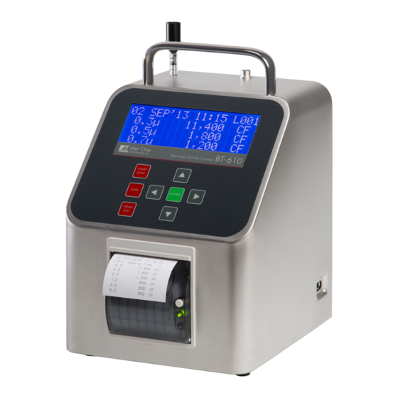
Introduction The BT-610 is a portable airborne particle counter with a small stable footprint. This allows you to move it around and set it down rather than holding it in your hand while sampling. The large character backlit LCD display provides easy viewing from distances exceeding 3 meters. - Page 6 Iso-Kinetic Inlet BT-610 Zero Filter MOI P/N: G3111 MOI P/N: G3110 Manual Battery Charger Particle View Software CD MOI P/N: BT-610- MOI P/N: 80643 9800 Calibration USB Cable Comet Software Certificate MOI P/N: BT-610- MOI P/N: 500784 MOI P/N: 80248...
- Page 7 BT-610 Optional Equipment Temperature & Humidity Probe MOI P/N: G3120 Dwyer Ball Flow Meter Serial Cable MOI P/N: 550065 MOI P/N: 9801 Figure 2 – Optional Equipment Page 6 BT-610-9800 Rev C...
-
Page 8: Layout
2.2. Layout Figure 3 shows the layout of the BT-610 and the following table provides a description of the components. Carrying Handle Inlet Nozzle Temp/RH Connector Display Keyboard Printer Page 8 BT-610-9800 Rev C... - Page 9 Power Switch Charger Jack USB for Data Transfer (on side) RS-232 USB I/O RS 485 Analog Out Figure 3 – BT-610 Layout Page 9 BT-610-9800 Rev C...
-
Page 10: Default Settings
RS-232 2.4. Initial Operation Before operating the BT-610 for the first time, it is recommended that the unit be fully charged. Information regarding battery charging is found in Section 7. Complete the following steps to verify proper operation. 1. Press the top of the power switch to turn on power. -
Page 11: User Interface
4.1. Power Up The BT-610 power is controlled by a switch located on the back of the unit. To power up the unit move the switch to the on position (up). The first screen shown on power up is the Startup Screen (Figure 4). This screen displays the product type and company website for approximately 2 seconds before loading the Operate Screen. -
Page 12: Printer Operation
Place a roll of paper in the printer bay with the free end up and coming from the back of the roll. Close the printer door and the green indicator light should light. Press the white button on printer to manually advance the paper. See Section 5.5 for Printer Operation. Page 12 BT-610-9800 Rev C... -
Page 13: Operate Screen
(see Section 5.4). The Favorites setting configures the display and printer for two sizes however the BT-610 still counts and buffers all six particle sizes. Sample data for all six channels is available via the serial port (Section 8) or by viewing count history on the display (Section 4.3.4). -
Page 14: Sampling
24C RH Figure 9 – Operate Screen (Sampling) 4.3.3. Sample Status The top line of the Operate Screen displays the status of the BT-610 while the unit is sampling. The following table shows the various status messages and their meaning: Status Description STARTING…... -
Page 15: Warnings / Errors
Operate Screen or the main menu. 4.4.2. Real-Time Output BT-610 provides real-time output on the serial port at the end of each sample. The format of the output is controlled by the Serial Output setting (Section 5.4). -
Page 16: Sample Timing
PRINTER FAVORITES SET SIZES CALIBRATE FLOW SET CLOCK SET CONTRAST ABOUT Figure 13 – BT-610 Main Menu Menu Item Description Press Enter to navigate to… View / change location number, auto / single SAMPLE SETUP Sample Setup Screen mode, sample time and hold time. -
Page 17: Edit Main Menu Items
Hold time is 60 seconds or less. The pump will stop after each sample, and start a few seconds before the next sample, if the Hold time is greater than 60 seconds. Hold times greater than 60 seconds will increase pump life. Page 17 BT-610-9800 Rev C... -
Page 18: Samples
Figure 15 – Settings Screen 5.3.1. Count Units The BT-610 supports total counts (TC), particles per liter (/L), particles per cubic foot (CF) and particles per cubic meter (M3). Particle count information updates while the unit is sampling. Concentration values (/L, CF, M3) are time dependent so these values may fluctuate early in the sample;... -
Page 19: Report Type
300 – 38400. 5.4.3. Serial Output Mode The Serial Out setting controls the behavior of the BT-610 serial output. The modes are RS232, RS485, Printer or Network (see Section 7 for serial communication protocol). The following table lists the Serial Output settings and describes their meanings. -
Page 20: Favorites Screen
Figure 19 shows the analog output connector pin assignments. GND pins are signal ground. A1 and A2 are Analog Output 1 and Analog Output 2 which are associated to Favorite 1 and Favorite 2 respectively (see Section 5.6.2). Figure 19 – Analog Output Connector Page 20 BT-610-9800 Rev C... -
Page 21: Calibrate Flow Screen
5.7. Calibrate Flow Screen The BT-610 has a factory calibrated flow rate of 0.1 CFM (2.83 LPM). Under normal circumstances, the integrated flow control system will maintain flow within +/- 5% of this flow rate. Use the following procedure to calibrate the flow rate when a periodic flow rate check (Section 9.1.2) indicates a flow rate error greater than +/- 5%. -
Page 22: Set Contrast Screen
To access data options (copy data, view available memory, recall data and print data), simply press the Data key to navigate to the Data Screen. Figure 25 shows the Data Screen. COPY TO USB DRIVE RECALL DATA PRINT DATA MEMORY Figure 25 – Data Screen Page 22 BT-610-9800 Rev C... -
Page 23: Copy To Usb Drive
6.1. Copy to USB Drive Figure 26 shows the Copy Data Screen. The BT-610 will copy all data from the displayed date/time to current time. Initially, the date/time will be the first sample record so all records will be copied. To reduce transfer time, press Enter and change the date/time to a more recent date/time. -
Page 24: Printing Sample Data
PRINTING STATUS SCANNING...15 PRINTING...10 FINISHED! Figure 30 – Printing Status Screen Pressing the ESC button cancels the data printing and loads the menu. The format of the print is dependent upon the report setting (Section 5.2.4). Page 24 BT-610-9800 Rev C... -
Page 25: Memory Screen
To charge the battery, connect the battery charger to an AC power outlet and the DC plug to the socket on the back of the BT-610. The battery charger is universal and will work with power line voltages of 100 to 240 volts, 50 to 60 Hz. The battery charger LED indicator will be Red when charging and Green when fully charged. -
Page 26: Serial Communications
The following sections discuss the various serial communications. ATTENTION: The USB drivers must be installed before connecting the BT-610 USB port to your computer. If the supplied drivers are not installed first, Windows may install generic drivers that are not compatible with this product. -
Page 27: User Mode
8.2. Real Time Output The real time output occurs when the unit finishes a sample. The output format is either a comma separated value (CSV) or a printer style depending on the Serial Report mode. Page 27 BT-610-9800 Rev C... -
Page 28: Comma Separated Value (Csv)
31790 Note 2 Temperature (C,F) Note 2 & Note 3 RH (%) Note 3 Location Sample Time (0-9999 seconds) Favorite 1 Size Note 4 Favorite 2 Size Note 4 Status Bits (see below) Note 5 Page 28 BT-610-9800 Rev C... -
Page 29: Printer Style
For additional information on networking commands and addressing refer to the BT- 610-9801 Networking Supplement. Figure 32 shows the RS485 connector location and pin assignments. Figure 33 shows a RS-485 network wiring diagram. Page 29 BT-610-9800 Rev C... -
Page 30: Maintenance
Due to the nature of the instrument, there are no customer serviceable components in the BT-610. The case of the BT-610 should never be removed or opened for any reason. Opening or removing the case of the BT-610 voids the warranty and may result in exposure to laser radiation, which can cause eye injury. -
Page 31: Zero Count Test
4. The flow rate can be adjusted using the front panel (see Section 5.7) 9.1.3. Annual Calibration The BT-610 should be sent back to Met One Instruments yearly for calibration and inspection. The annual calibration cannot be performed by the customer because this calibration requires specialized equipment and a skilled technician. -
Page 32: Troubleshooting
The BT-610 case should never be removed or opened for any reason. Opening or removing the case will void the warranty and may result in exposure to laser radiation, which can cause eye injury. -
Page 33: Specifications
Battery Charger (P/N 80643) Iso-kinetic Sample Probe (P/N G3110) Zero Particulate Filter (P/N G3111) Printer Paper (2 Rolls) (P/N 750514) Optional RH & Temperature Probe (P/N G3120) Flow Meter (P/N 9801) Serial Cable (P/N 550065) Page 33 BT-610-9800 Rev C... -
Page 34: Warranty / Service
Any product found to be defective during the warranty period will, at the option of Met One Instruments, Inc., be replaced or repaired. In no case shall the liability of Met One Instruments, Inc. exceed the purchase price of the product.
Need help?
Do you have a question about the BT-610 and is the answer not in the manual?
Questions and answers