
Related Manuals for Met One Instruments AEROCET 532


Summary of Contents for Met One Instruments AEROCET 532
- Page 1 AEROCET 532 ANUAL Met One Instruments, Inc Corporate Sales & Service: 1600 NW Washington Blvd. Grants Pass, OR 97526 Tel (541) 471-7111 Fax (541) 471-7116 www.metone.com service@metone.com...
- Page 2 Copyright Notice AEROCET 532 Manual © Copyright 2021 Met One Instruments, Inc. All Rights Reserved Worldwide. No part of this publication may be reproduced, transmitted, transcribed, stored in a retrieval system, or translated into any other language in any form by any means without the express written permission of Met One Instruments, Inc.
-
Page 3: Table Of Contents
Memory ..........................17 5.3.3. K-Factors ........................... 18 5.3.4. Flow ........................... 19 5.3.5. Display ..........................20 5.4. Initial Setup Screen ......................... 20 5.4.1. Serial ..........................21 5.4.2. Clock ..........................22 5.4.3. Locations ........................... 23 AEROCET 532 Manual Rev A Page 3... - Page 4 8.2. Zero Count Test ........................28 8.3. Flow Rate Test......................... 28 8.4. Annual Calibration ........................29 8.5. Filter Change ........................... 29 8.6. Flash Upgrade ......................... 29 Troubleshooting ....................30 10. Specifications ...................... 31 AEROCET 532 Manual Rev A Page 4...
-
Page 5: Introduction
Introduction The AEROCET 532 is a full–featured, battery operated, handheld particle counter or mass monitor. In count mode, the unit will measure particle counts at eight fixed sizes (0.3 µm, 0.5 µm, 1.0 µm, 2.5 µm, 4.0 µm, 5.0 µm, 7.0 µm, and 10.0 µm). - Page 6 PN 400113 Rubber Boot Carrying Case PN 550537 PN 83549 Figure 1 – Standard Accessories Flow Meter Flow Meter Docking Station PN 9801 PN Swift 6.0 PN 83529 Figure 2 – Optional Accessories AEROCET 532 Manual Rev A Page 6...
-
Page 7: Layout
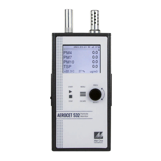
2.2. Layout The following figure shows the layout of the AEROCET 532 and provides a description of each of the components. AT/RH Sensor Isokinetic Probe Charging Jack USB C Port Rotary Dial Power Switch Keyboard Figure 3 – AEROCET 532 Layout... -
Page 8: Default Settings
115200 2.4. Initial Operation Before operating the AEROCET 532 for the first time, it is recommended that the unit be fully charged. Information regarding charging the battery is found in section 6 of this manual. Complete the following steps to verify proper operation. -
Page 9: Operation
4.2. Power Up AEROCET 532 power is controlled by a slide switch located on the left hand side of the unit. Move the power switch to the on position (towards the top of the case) to power up the unit. - Page 10 Figure 4 – Mass Operate Screen Figure 5 – Count Operate Screen AEROCET 532 Manual Rev A Page 10...
-
Page 11: Sampling
4.3.2. Sample Status The top of the Operate screen displays the status of the AEROCET 532 while the unit is sampling. The time remaining is shown at the top left of the screen. A status bar fills with green as time progresses. -
Page 12: Sample Related Functions
The hold time is used when the sample mode is set to auto (continuous sample). The hold time represents the time from the completion of the last sample to the start of the AEROCET 532 Manual Rev A Page 12... -
Page 13: Sample Timing
Toolbox Toolbox screen and display. View / change serial settings, clock, and Initial Setup Initial Setup screen locations. Display firmware version, serial number, About service contact, calibration date, and run About screen time. AEROCET 532 Manual Rev A Page 13... -
Page 14: Edit Menu Items
ESCAPE 5.2. Sample Setup Screen Figure 11 shows the Sample Setup Screen. The 6 parameters are covered in the following sections. AEROCET 532 Manual Rev A Page 14... -
Page 15: Location Id
The sample Mode controls single sample or continuous sampling as illustrated below. Selection Description Single The Single setting configures the unit for a single sample. The Continuous setting configures the unit for continuous Continuous sampling. AEROCET 532 Manual Rev A Page 15... -
Page 16: Count Mode
This setting will not appear on the Sample Setup screen if Single mode is selected. 5.3. Toolbox Screen Figure 12 shows the Toolbox screen. Figure 12 – Toolbox Screen AEROCET 532 Manual Rev A Page 16... -
Page 17: Units
The Memory screen allows the user to view available memory or to clear the memory. The AEROCET 532 memory is circular, meaning when the memory is full, the unit will start overwriting the oldest saved samples with new samples. Free shows the percent of space available for data storage. -
Page 18: K-Factors
The individual user k-factors for each mass channel can be set from 0.1 to 20.0. Figure 15 - K-Factor Screen The AEROCET 532 calibration is performed using ideal polystyrene latex (PSL) spheres, which provide a powerful tool for assessing the sensitivity, accuracy, resolution, and false count level. -
Page 19: Flow
Calculate the K-Factor for each particulate size fraction as the reference concentration divided by the AEROCET 532 light scatter concentration over the same time period. For example, if the reference total concentration was 51 μg/m and the AEROCET total concentration was 38 μg/m... -
Page 20: Display
1, 5, or 10 minutes. Figure 18 - Display Setup Screen 5.4. Initial Setup Screen Figure 19 shows the Initial Setup screen. AEROCET 532 Manual Rev A Page 20... -
Page 21: Serial
Figure 19 – Initial Setup Screen 5.4.1. Serial The Serial setting controls the behavior of the AEROCET 532 RS-485 serial output hardware available on the optional docking station. The following table lists the Serial settings and describes their meanings. Selection Description Unique ID assigned to each device for networking mode (1 –... -
Page 22: Clock
Press the dial to edit. Turn the dial to change, then press to confirm the change. Press the dial on the SET box to change the settings and return to the Initial Setup screen. Figure 21 - Clock Screen AEROCET 532 Manual Rev A Page 22... -
Page 23: Locations
About Screen Figure 23 shows the ABOUT screen. The ABOUT screen shows the manufacturer’s serial number, the firmware version, Met One Instruments, Inc. service email and phone number, date of last calibration, and run time. Figure 23 – About Screen... -
Page 24: Charging The Battery
Hz. A discharged battery pack will take approximately 2.5 hours to fully charge. When fully charged the battery inside the AEROCET 532 will power the unit for over 8 hours of continuous sampling. For continuous operation, operate the unit with the battery charger attached. - Page 25 Sample Mode. SM 0=Single, SM 1=Continuous Serial Number Sample Time. ST 0=1-min, ST 1=2-min, ST 2=5-min, ST 3=10-min, ST 4=15-min, ST 5=30-min, ST 6=1-hour. Temperature Units. TU 0=C, TU 1=F DISPTO Manual Display Timeout. 0=None, 1=1-min, 2=5-min, 3=10-min. AEROCET 532 Manual Rev A Page 25...
-
Page 26: Comma Separated Value (Csv)
Channel 6 Size 5.0 (TC, /L, CF, M3) 00000353 Channel 7 Size 7.0 (TC, /L, CF, M3) 00000353 Channel 8 Size 10 (TC, /L, CF, M3) +024.9 AT (C, F) RH (%) LOC1 Location 0060 Seconds 0000 Status AEROCET 532 Manual Rev A Page 26... -
Page 27: Mass Format
AT (C, F) RH (%) LOC1 Location 0060 Seconds 0000 Status Status Bits Value Condition OK (no alarms or errors) Not used IOP Alarm (Laser) Not used Not used Temperature Sensor Alarm Pressure Sensor Alarm AEROCET 532 Manual Rev A Page 27... -
Page 28: Maintenance
Due to the nature of the instrument, there are minimal customer serviceable components in the AEROCET 532. The case of the AEROCET 532 should never be removed or opened for any reason. Opening or removing the case of the AEROCET 532 voids the warranty and may result in exposure to laser radiation, which can cause eye injury. -
Page 29: Annual Calibration
8.4. Annual Calibration The AEROCET 532 should be sent back to Met One Instruments yearly for calibration and inspection. The annual calibration cannot be performed by the customer because this calibration requires specialized equipment and a skilled technician. Met One Instruments maintains a calibration facility for calibrating particle counters according to industry accepted methods such as ISO and NIST. -
Page 30: Troubleshooting
• Defective or worn out battery Battery does not hold a • Send to service center • Defective charger charge • Charge battery – the • Low Battery Low battery unit can sample while running on the charger AEROCET 532 Manual Rev A Page 30... -
Page 31: Specifications
AC Adapter/Battery Charger Iso-kinetic Sample Probe RH and Temperature Probe Carrying Case Rubber Boot Zero Particulate Filter Optional Flow Meter kit (PN 9801) Digital flow meter (PN Swift 6.0) Docking Station (PN 83529) AEROCET 532 Manual Rev A Page 31... - Page 32 AEROCET 532 Manual Rev A Page 32...
Need help?
Do you have a question about the AEROCET 532 and is the answer not in the manual?
Questions and answers