Table of Contents
Advertisement
WARNING: If the information in this manual is not
followed exactly, a fire or explosion may result causing
property damage, personal injury or loss of life.
— Do not store or use gasoline or other flammable va-
pors and liquids in the vicinity of this or any other
appliance.
— WHAT TO DO IF YOU SMELL GAS
• Do not try to light any appliance.
• Do not touch any electrical switch; do not use any
phone in your building.
• Immediately call your gas supplier from a neighbor's
phone. Follow the gas supplier's instructions.
• If you cannot reach your gas supplier, call the fire
department.
— Installation and service must be performed by a quali-
fied installer, service agency or the gas supplier.
WARNING: This appliance is equipped for Natural and
Propane gas. Field conversion is not permitted other than
between natural or propane gases.
Questions, problems, missing parts? Before returning to your retailer, call
our customer service department at 1-855-607-6557, 8:00 am - 4:30 pm EST,
Monday through Friday or email info@factorybuysdirect.com
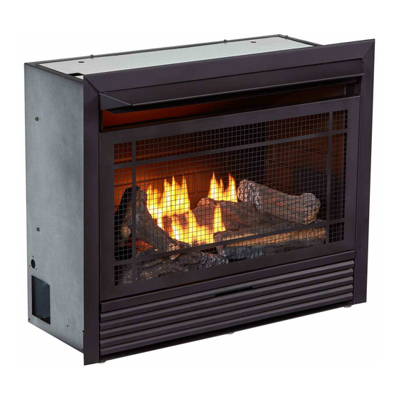
VENT-FREE GAS FIREPLACE
INSERT
OWNER'S OPERATION AND
INSTALLATION MANUAL
MODEL FDF300R
This insert can be used in the mantel and
fireplace systems CM300-1
PFS
®
US
Advertisement
Table of Contents

Related Manuals for Duluth Forge FDF300R


Summary of Contents for Duluth Forge FDF300R
- Page 1 VENT-FREE GAS FIREPLACE INSERT OWNER’S OPERATION AND INSTALLATION MANUAL MODEL FDF300R This insert can be used in the mantel and fireplace systems CM300-1 ® WARNING: If the information in this manual is not followed exactly, a fire or explosion may result causing property damage, personal injury or loss of life.
-
Page 2: Table Of Contents
TABLE OF CONTENTS Safety ............3 Operation ..........19 Specifications ..........4 Inspecting Burners........23 Qualified Installing Agency ......5 Care And Maintenance ......24 Product Features ........5 Accessories ..........25 Local Codes..........5 Troubleshooting ........26 Unpacking..........6 Service Hints ........... -
Page 3: Safety
SAFETY IMPORTANT: Read this owner’s WARNING: Any change to manual carefully and completely this heater or its controls can before trying to assemble, op- be dangerous. erate, or service this heater. Improper use of this heater can WARNING: Do not allow fans cause serious injury or death to blow directly into fireplace. -
Page 4: Specifications
Poor combustion and higher levels of carbon monoxide may result. SPECIFICATIONS Model FDF300R Gas Type Natural Gas Propane Gas Ignition Piezo Ignitor... -
Page 5: Qualified Installing Agency
QUALIFIED INSTALLING AGENCY Only a qualified agency should install and a) Installing, testing, or replacing gas piping replace gas piping, gas utilization equipment or accessories, and repair and equipment ser- b) Connecting, installing, testing, repairing, vicing. The term “qualified agency” means any or servicing equipment;... -
Page 6: Unpacking
UNPACKING 1. Remove top inner pack. 7. Remove log set by cutting plastic ties. 2. Tilt carton so that heater is upright. 8. Carefully unwrap log. 3. Remove protective side packaging. 9. Check for any shipping damage. If heater or log is damaged, promptly inform your 4. -
Page 7: Air For Combustion And Ventilation
AIR FOR COMBUSTION AND VENTILATION WARNING: This heater shall WARNING: This heater shall not be installed in a room or not be installed in a confined space space unless the required vol- or unusually tight construction ume of indoor combustion air unless provisions are provided is provided by the method de- for adequate combustion and... - Page 8 AIR FOR COMBUSTION AND VENTILATION VENTILATION AIR Ventilation Air From Inside Building This fresh air would come from an adjoining 1 and 2, Figure 2). You can also remove door unconfined space. When ventilating to an into adjoining room (see option 3, Figure 2). adjoining unconfined space, you must provide Follow the National Fuel Gas Code, ANSI two permanent openings: one within 12"...
-
Page 9: Installation
INSTALLATION IMPORTANT: Vent-free heaters add moisture NOTICE: This heater is intended to the air. Although this is beneficial, installing for use as supplemental heat. heater in rooms without enough ventilation air Use this heater along with your may cause mildew to form too much moisture. primary heating system. - Page 10 INSTALLATION GAS SELECTION Insert Gas Fitting Insert Gas Fitting This appliance is factory for Propane/LP Gas for Natural Gas preset for propane/LP gas. No changes are required for connecting to propane/LP. Only a qualified installer or service technician can perform gas selec- tion and connecting to gas supply.
- Page 11 INSTALLATION 2. Apply thread sealant to the threads on Use only the cap supplied on the the connection fitting. While pushing in, regulator. Do not use an off the rotate the fitting clockwise until the threads shelf pipe plug. This can damage engage the regulator.
- Page 12 INSTALLATION BUILT-IN FIREPLACE INSTALLATION WARNING: Do not allow any combustible materials to overlap the firebox front. WARNING: Do not allow combustible or noncombustible 3/4" Clearance to Facia materials to cover any necessary " Clearance to Sides, Back and Top openings like louvered slots. "...
- Page 13 INSTALLATION 3. Attach gas line to fireplace gas regulator. See Connecting to Gas Supply, page 14. 4. Check all gas connections for leaks. See Checking Gas Connections, page 16. IMPORTANT: When finishing your firebox, combustible materials such as wall board, gypsum board, sheet rock, drywall, plywood, etc, must have 1/2"...
- Page 14 INSTALLATION CONNECTING TO GAS SUPPLY WARNING: A qualified ser- CAUTION: Avoid damage to vice technician must connect regulator. Hold gas regulator heater to gas supply. Follow all with wrench when connecting local codes. into gas piping and/or fittings. WARNING: This appliance CAUTION: Use pipe joint requires a 3/8"...
- Page 15 INSTALLATION The installer must supply an external regula- Install sediment trap in supply line as shown tor. The external regulator will reduce incom- in Figure 12. Place sediment trap where it is ing gas pressure. You must reduce incoming within reach for cleaning. Place sediment trap gas pressure to between 11"...
- Page 16 INSTALLATION CHECKING GAS CONNECTIONS Test Pressures Equal To or Less Than WARNING: Test all gas piping 1/2 PSIG (3.5 kPa) and connections for leaks after 1. Close equipment shutoff valve (see Fig- installing or servicing. Correct ure 15). all leaks at once. 2.
- Page 17 INSTALLATION PRESSURE TESTING HEATER GAS CONNECTIONS 1. Open equipment shutoff valve (see Figure 17, page 16). Apply a noncorrosive leak 15, page 16). detection fluid to all joints. Bubbles form- ing show a leak. 2. Open main gas valve located on or near gas meter for natural gas or open pro- 5.
- Page 18 INSTALLATION INSTALLING BATTERIES Receiver and Remote Control CAUTION: Do not mix old and Batteries are required in both the Remote new batteries. Do not mix alka- Control (Transmitter) (2 AAA size) and Re- ceiver (4 AA size) (see Figure 21). line, standard (carbon - zinc), or Note: Be sure batteries are placed correctly.
-
Page 19: Operation
OPERATION FOR YOUR SAFETY READ BEFORE LIGHTING not use any phone in your building. WARNING: If you do not fol- • Immediately call your gas supplier low these instructions exactly, a from a neighbor’s phone. Follow the fire or explosion may result caus- gas supplier’s instructions. - Page 20 OPERATION 6. With control knob pressed in, push down 9. Turn control knob counterclockwise and release ignitor button. This will light to desired heating level. The main burner pilot. The pilot is attached to the rear should light. Set control knob to any heat of the front of burner.
- Page 21 OPERATION REMOTE CONTROL SYSTEM Programming the Remote and Receiver Key Settings The remote and receiver must be “learned” ON - Operates unit to on position, manually to one another. operated solenoid ON. To prepare the receiver box for learning, use OFF - Operates unit to off position, manually a pen or small screwdriver to gently press operated solenoid OFF.
- Page 22 OPERATION Setting°F/°C Scale 2. Press and hold the SET key until the de- The factory setting for temperature is °F. To sired set temperature is reached. The LCD change this setting to °C, press the ON key screen set numbers will increase from 45° and the OFF key on the remote control at the to 99°...
-
Page 23: Inspecting Burners
INSPECTING BURNERS IMPORTANT: Owner’s should check pilot flame pattern and burner flame pattern often. Incorrect flame patterns indicate the need for cleaning (see Care and Maintenance, page 24) or service. WARNING: Only a qualified service person should service and repair heater. This includes maintenance requiring replacement or alteration of components. -
Page 24: Care And Maintenance
CARE AND MAINTENANCE WARNING: Turn off heater and let cool before servicing. CAUTION: You must keep control areas, burner, and circulating air passageways of heater clean. Inspect these areas of heater before each use. Have heater inspected yearly by a qualified service techni- cian. -
Page 25: Accessories
CARE AND MAINTENANCE ODS/PILOT Ignitor Natural Gas Thermocouple Use a vacuum cleaner, pressurized air, or a Electrode Burner small, soft bristled brush to clean. Propane/LP A yellow tip on the pilot flame indicates dust Gas Burner and dirt in the pilot assembly. There is a small pilot air inlet hole about 2"... -
Page 26: Troubleshooting
TROUBLESHOOTING WARNING: If you smell gas: • Shut off gas supply. • Do not try to light any appliance. • Do not touch any electrical switch; do not use any phone in your building. • Immediately call your gas supplier from a neighbor’s phone. Fol- low the gas supplier’s instructions. - Page 27 TROUBLESHOOTING Problem Possible Cause Corrective Action When ignitor button is 1. Ignitor electrode is posi- 1. Replace electrode. pressed in, there is no tioned wrong. Ignitor elec- spark at ODS/pilot trode is broken. 2. Ignitor electrode is not con- 2. Replace ignitor cable nected to ignitor cable.
- Page 28 TROUBLESHOOTING Problem Possible Cause Corrective Action Burner(s) does not light 1. Burner orifice is clogged. 1. Clean burner orifice (see after ODS/pilot is lit Care and Maintenance, page 24) or replace burner orifice. 2. Burner orifice diameter is too 2. Replace burner orifice. small.
-
Page 29: Service Hints
TROUBLESHOOTING Problem Possible Cause Corrective Action Heater produces a click- 1. Metal is expanding while 1. This is common with most ing/ticking noise just after heating or contracting while heaters. If noise is exces- burner is lit or shut off. cooling. -
Page 30: Parts
PARTS MODEL FDF300R www.factorybuysdirect.com 200253-01A... -
Page 31: Replacement Parts
PARTS MODEL FDF300R This list contains replaceable parts for your heater. When ordering replacement parts, follow the instructions listed under Replacement Parts of this manual. ITEM PART # DESCRIPTION MRT-01 Remote Control Valve RVD88-Y-4/9 Regulator Burner Assembly ND0310A-400-P PIMDNI-01 Piezo Ignitor... -
Page 32: Warranty
WARRANTY KEEP THIS WARRANTY Model _______________________________ Serial No. ____________________________ Date Purchased _______________________ Keep receipt for warranty verification. REGISTER YOUR PRODUCT AT WWW.FACTORYBUYSDIRECT.COM FACTORY BUYS DIRECT LIMITED WARRANTIES New Products Standard Warranty: Factory Buys Direct warrants this new product and any parts thereof to be free from defects in material and workmanship for a period of one (1) year from the date of first purchase from an authorized dealer provided the product has been installed, maintained and operated in accordance with Factory Buys Direct’s warnings and instructions.
Need help?
Do you have a question about the FDF300R and is the answer not in the manual?
Questions and answers
My insert keeps beeping
My pilot light starts out blue and gradually turns yellow and goes out. What would cause this?
Your Duluth Forge FDF300R insert beeps when batteries are correctly installed in the receiver box and charged. If you do not hear a beep, the batteries may need to be replaced.
This answer is automatically generated
My unit will run for a couple of minutes and then fade out. Pilot goes out as well. I have blown and cleaned The ODS component and it will light up and run for a little while and die out again. I installed this unit this year after rehabbing this home. It has no run time as it won’t stay operational. I have good combustion fresh air around the fireplace. I **** running 100lb propane cylinder full of fuel. I have no gas leaks. Could it be the ODS or regulator in this heater?
Yes, the ODS (Oxygen Depletion Sensor) or the regulator could be causing the Duluth Forge FDF300R to run for a couple of minutes and then fade out. Possible reasons include:
- A faulty or dirty ODS/pilot assembly, which may prevent a stable flame.
- Incorrect inlet gas pressure or a damaged inlet regulator, leading to inconsistent fuel supply.
- A pilot flame not properly touching the thermocouple, which can cause it to cool and shut off the gas supply.
Checking and replacing the ODS/pilot assembly or the inlet gas regulator may resolve the issue.
This answer is automatically generated