Table of Contents
Advertisement
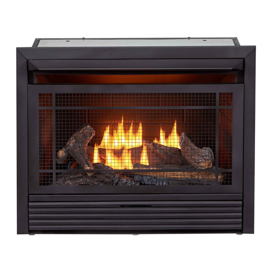
VENT-FREE GAS
FIREPLACE INSERT
OWNER'S OPERATION AND
INSTALLATION MANUAL
SKU 170121
MODEL FDF300T
Visit our website to view optional
fireplace mantels that can be used
with this fireplace insert.
WARNING: If the information in this manual is not
followed exactly, a fire or explosion may result causing
property damage, personal injury or loss of life.
— Do not store or use gasoline or other flammable va-
pors and liquids in the vicinity of this or any other
appliance.
— WHAT TO DO IF YOU SMELL GAS
• Do not try to light any appliance.
• Do not touch any electrical switch; do not use any
phone in your building.
• Immediately call your gas supplier from a neighbor's
phone. Follow the gas supplier's instructions.
• If you cannot reach your gas supplier, call the fire
department.
— Installation and service must be performed by a quali-
fied installer, service agency or the gas supplier.
WARNING: This appliance is equipped for Natural and
Propane gas. Field conversion is not permitted other than
between natural or propane gases.
Questions, problems, missing parts? Before returning to your retailer, call
our customer service department at 1-855-607-6557, 8:00 am - 4:30 pm EST,
Monday through Friday or email contact@factorybuysdirect.com
Advertisement
Table of Contents

Related Manuals for Duluth Forge FDF300T


Summary of Contents for Duluth Forge FDF300T
- Page 1 VENT-FREE GAS FIREPLACE INSERT OWNER’S OPERATION AND INSTALLATION MANUAL SKU 170121 MODEL FDF300T Visit our website to view optional fireplace mantels that can be used with this fireplace insert. WARNING: If the information in this manual is not followed exactly, a fire or explosion may result causing property damage, personal injury or loss of life.
-
Page 2: Table Of Contents
TABLE OF CONTENTS Safety ............3 Operation ..........18 Specifications ..........4 Inspecting Burners........20 Qualified Installing Agency ......5 Care And Maintenance ......22 Product Features ........5 Troubleshooting ........24 Local Codes..........5 Parts ............28 Unpacking..........6 Replacement Parts ........ -
Page 3: Safety
SAFETY IMPORTANT: Read this owner’s WARNING: Any change to manual carefully and completely this heater or its controls can before trying to assemble, op- be dangerous. erate, or service this heater. Improper use of this heater can WARNING: Do not allow fans cause serious injury or death to blow directly into fireplace. -
Page 4: Specifications
8. Do not use heater if any part has been under water. Immediately call a qualified service technician to inspect the room SPECIFICATIONS SKU 170121 Model FDF300T Gas Type Natural Gas Propane Gas Ignition Piezo Ignitor... -
Page 5: Qualified Installing Agency
QUALIFIED INSTALLING AGENCY Only a qualified agency should install and a) Installing, testing, or replacing gas piping replace gas piping, gas utilization equipment or accessories, and repair and equipment ser- b) Connecting, installing, testing, repairing, vicing. The term “qualified agency” means any or servicing equipment;... -
Page 6: Unpacking
UNPACKING 1. Remove hood from the top foam. 7. Remove log set by cutting plastic ties. 2. Remove the top corner foam. 8. Carefully unwrap log. 3. Remove heater from carton. 9. Check for any shipping damage. If heater or log is damaged, promptly inform your 4. -
Page 7: Air For Combustion And Ventilation
AIR FOR COMBUSTION AND VENTILATION WARNING: This heater shall WARNING: This heater shall not be installed in a room or not be installed in a confined space space unless the required vol- or unusually tight construction ume of indoor combustion air unless provisions are provided is provided by the method de- for adequate combustion and... - Page 8 AIR FOR COMBUSTION AND VENTILATION VENTILATION AIR Ventilation Air From Inside Building This fresh air would come from an adjoining 1 and 2, Figure 2). You can also remove door unconfined space. When ventilating to an into adjoining room (see option 3, Figure 2). adjoining unconfined space, you must provide Follow the National Fuel Gas Code, ANSI two permanent openings: one within 12"...
-
Page 9: Installation
INSTALLATION IMPORTANT: Vent-free heaters add moisture NOTICE: This heater is intended to the air. Although this is beneficial, installing for use as supplemental heat. heater in rooms without enough ventilation Use this heater along with your air may cause mildew to form from too much primary heating system. - Page 10 INSTALLATION GAS SELECTION Insert Gas Fitting Insert Gas Fitting This appliance is factory for Propane/LP Gas for Natural Gas preset for propane/LP gas. No changes are required for connecting to propane/LP. Only a qualified installer or service technician can perform gas selec- tion and connecting to gas supply.
- Page 11 INSTALLATION 2. Apply thread sealant to the threads on a Use only the cap supplied on the 3/8" NPT brass connection fitting. While regulator. Do not use an off the pushing in, rotate the fitting clockwise until shelf pipe cap. This can damage the threads engage the regulator.
- Page 12 INSTALLATION BUILT-IN FIREPLACE INSTALLATION WARNING: Do not allow any combustible materials to overlap the firebox front. WARNING: Do not allow combustible or noncombustible 3/4" Clearance to Facia materials to cover any necessary " Clearance to Sides, Back and Top openings like louvered slots. "...
- Page 13 INSTALLATION 3. Attach gas line to fireplace gas regulator. See Connecting to Gas Supply, page 14. 4. Check all gas connections for leaks. See Checking Gas Connections, page 16. IMPORTANT: When finishing your firebox, combustible materials such as wall board, gypsum board, sheet rock, drywall, plywood, etc, must have 1/2"...
- Page 14 INSTALLATION CONNECTING TO GAS SUPPLY WARNING: A qualified ser- CAUTION: Avoid damage to vice technician must connect regulator. Hold gas regulator heater to gas supply. Follow all with wrench when connecting local codes. into gas piping and/or fittings. WARNING: This appliance re- CAUTION: Use pipe joint quires a 3/8"...
- Page 15 INSTALLATION The installer must supply an external regula- Install sediment trap in supply line as shown tor. The external regulator will reduce incom- in Figure 12. Place sediment trap where it is ing gas pressure. You must reduce incoming within reach for cleaning. Place sediment trap gas pressure to between 11"...
- Page 16 INSTALLATION CHECKING GAS CONNECTIONS Test Pressures Equal To or Less Than WARNING: Test all gas piping 1/2 PSIG (3.5 kPa) and connections for leaks after 1. Close equipment shutoff valve (see Fig- installing or servicing. Correct ure 15). all leaks at once. 2.
- Page 17 INSTALLATION 4. Check all joints from equipment shutoff 6. Light heater (see Lighting Instructions on valve to control valve (see Figure 16 or page 19). Check all other internal joints 17, page 16). Apply a noncorrosive leak for leaks. detection fluid to all joints. Bubbles form- 7.
-
Page 18: Operation
INSTALLATION BATTERY INSTRUCTIONS Unscrew ignitor cap and install a AAA battery CAUTION: Do not dispose of with the + pointing out. Replace cap. batteries in fire, batteries may explode or leak. • Battery is included. • Remove battery when depleted. Battery •... - Page 19 OPERATION LIGHTING INSTRUCTIONS Note: If pilot does not stay lit, refer to WARNING: You must oper- Troubleshooting, pages 24 though 27. ate this heater with the screen Also contact a qualified service technician in place. Make sure screen is or gas supplier for repairs. Until repairs are made, light pilot with match.
-
Page 20: Inspecting Burners
OPERATION THERMOSTAT CONTROL OPERATION The thermostatic control used on this model room temperature drops below the set tem- differs from standard thermostats. Standard perature. The control knob can be set to any thermostats simply turn the burner on and off. comfort level between HIGH (5) and LOW (1). - Page 21 INSPECTING BURNERS Natural Gas Shown Natural Gas Shown 3-3.5" WC 8-11" WC 3-3.5" WC 8-11" WC Approx. 3"-6" Above Top of Logs Figure 22 - Correct Pilot Flame Pattern Figure 23 - Incorrect Pilot Flame Pattern (Natural Gas shown) (Natural Gas shown) BURNER FLAME PATTERN Figure 24 shows a correct burner flame pattern.
-
Page 22: Care And Maintenance
CARE AND MAINTENANCE WARNING: Turn off heater and let cool before servicing. CAUTION: You must keep control areas, burner, and circulating air passageways of heater clean. Inspect these areas of heater before each use. Have heater inspected yearly by a qualified service techni- cian. - Page 23 CARE AND MAINTENANCE ODS/PILOT Ignitor Natural Gas Thermocouple Use a vacuum cleaner, pressurized air, or a Electrode Burner small, soft bristled brush to clean. Propane/LP A yellow tip on the pilot flame indicates dust Gas Burner and dirt in the pilot assembly. There is a small pilot air inlet hole about 2"...
-
Page 24: Troubleshooting
TROUBLESHOOTING WARNING: If you smell gas: • Shut off gas supply. • Do not try to light any appliance. • Do not touch any electrical switch; do not use any phone in your building. • Immediately call your gas supplier from a neighbor’s phone. Fol- low the gas supplier’s instructions. - Page 25 TROUBLESHOOTING Problem Possible Cause Corrective Action When ignitor button is 1. Ignitor electrode is posi- 1. Replace electrode. pressed in, there is no tioned wrong. Ignitor elec- spark at ODS/pilot trode is broken. 2. Ignitor electrode is not con- 2. Replace ignitor cable nected to ignitor cable.
- Page 26 TROUBLESHOOTING Problem Possible Cause Corrective Action Burner(s) does not light 1. Burner orifice is clogged. 1. Clean burner orifice (see after ODS/pilot is lit Care and Maintenance, page 22). 2. Inlet gas pressure is too low. 2. Contact local gas supplier. Delayed ignition of 1.
- Page 27 TROUBLESHOOTING Problem Possible Cause Corrective Action Heater produces a click- 1. Metal is expanding while 1. This is common with most ing/ticking noise just after heating or contracting while heaters. If noise is exces- burner is lit or shut off. cooling.
-
Page 28: Parts
PARTS SKU 170121 MODEL FDF300T www.factorybuysdirect.com 200415-01A... - Page 29 PARTS SKU 170121 MODEL FDF300T This list contains replaceable parts for your heater. When ordering replacement parts, follow the instructions listed under Replacement Parts on page 30 of this manual. ITEM PART # DESCRIPTION 161130-01 T-Stat Valve 161188-01 Regulator Burner Assembly...
-
Page 30: Replacement Parts
REPLACEMENT PARTS Note: Use only original replacement parts. This will protect your warranty coverage for parts replaced under warranty. PARTS UNDER WARRANTY Contact authorized dealers of this product. • Model and serial number of your heater If they can’t supply original replacement •... -
Page 31: Service Hints
SERVICE HINTS When Gas Pressure Is Too Low • pilot will not stay lit • burners will have delayed ignition • fireplace will not produce specified heat • propane/LP gas supply might be low (propane/LP units only) You may feel your gas pressure is too low. If so, contact your local gas supplier. TECHNICAL SERVICE You may have further questions about installation, operation, or troubleshooting. -
Page 32: Warranty
WARRANTY KEEP THIS WARRANTY Model _______________________________ Serial No. ____________________________ Date Purchased _______________________ Keep receipt for warranty verification. REGISTER YOUR PRODUCT AT WWW.FACTORYBUYSDIRECT.COM FACTORY BUYS DIRECT LIMITED WARRANTIES New Products Standard Warranty: Factory Buys Direct warrants this new product and any parts thereof to be free from defects in material and workmanship for a period of one (1) year from the date of first purchase from an authorized dealer provided the product has been installed, maintained and operated in accordance with Factory Buys Direct’s warnings and instructions.
Need help?
Do you have a question about the FDF300T and is the answer not in the manual?
Questions and answers