Advertisement
Quick Links
Advertisement

Related Manuals for Marstair MB Series


Summary of Contents for Marstair MB Series
- Page 1 USER MANUAL MB & MW SERIES AIR COOLER AND UNIT COOLER 56808001-02...
- Page 2 Cold Room Evaporator Manual Index Introduction 1.1 Model Explanation System (Product Description, Application Area, Working Principle) 3 2.1 MBMT/MBLT Type Cold Room Evaporators 2.2 MWMT/MWLT Type Cold Room Evaporators Safety Instructions 3.1 Positioning 3.2 Installation 3.3 Piping 3.4 Connections 3.5 Drainage 3.6 Fan 3.7 Refrigerant Charge 3.8 Sound Level...
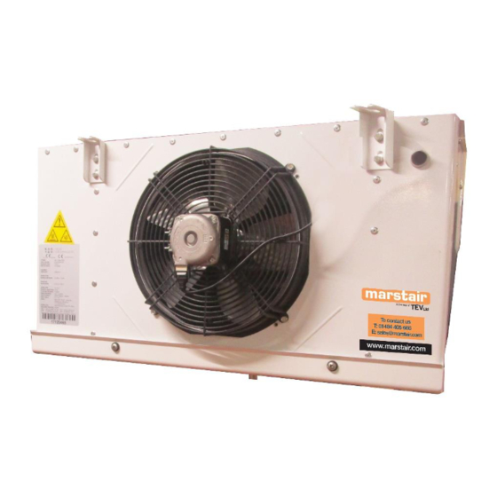
- Page 3 The data plate gives information for the evaporator unit only This manual includes Marstair production of MB and MW types of Cold Room Evaporators which are used in the cooling sector. MB are box type and MW are wedge type ceiling mounted coolers.
- Page 4 During the cooling process air humidity may cause icing problems and defrosting may be required. Coolers are manufactured with electric defrost. Marstair Box type Cold room evaporator MB type cold room evaporators are manufactured for use in small and medium commercial areas.
- Page 5 5834 1567 520 426 1295 438 420 345 Marstair Wedge Type Cold Room Evaporator MW type cold room evaporators are manufactured to be ceiling mounted. They have fans with Ø300mm fan diameter and they are configurable with up to 3 fans. 4,2mm and 7,00mm are the standard fin spacing.
- Page 6 COIL DATA DIMENSIONS MWMT130B 1738 685 370 630 18 MWMT130C 2051 685 370 630 19 MWMT230B 3552 1260 685 370 498 - 630 30 MWMT230C 4378 1260 685 370 498 - 630 31 MWMT230E 5175 1260 685 370 498 - 630 34 MWMT330C 6563 1740 685 370...
- Page 7 Positioning • Make sure the air circulation fulfills the entire room. •Keep enough space for maintenance. Make sure the side panels and drainage tray are easily removable •Avoid mounting evaporators above doors. • Ensure optimum piping and drainage lines • Sample dimensions for positioning are given below in the table. (H: Evaporator Height). Please consult your project firm for exact dimensions.
- Page 8 Installation •Ensure that product mounting is level and stable. Figure 3.2.1 Connector 3.3 Piping • Be careful choosing and assembling suction line and its parts for piping. Optimum piping has enough refrigerant or velocity for effective circulation and has a pressure drop which does not reduce system performance.
- Page 9 Figure 3.4.2 Correct and incorrect connections • Do not hold welding torch directly to the product Figure 3.4.3 Correct usage of welding flame 56808001-02...
- Page 10 3.5 Drainage • Make sure the drainage line is gradually lower than the drainage pan, so drainage line must be downward sloping for easy drainage. Figure 6.8 Example of recommended drainage line 3.6 Fan • MB types have inflow fans, MW types have outflow fans. •...
- Page 11 3.8 Sound Level • In the below tables, Sound level of products with standard fans are given in db(A) (decibels) for 3 m distance. Values are obtained from fan manufacturers, and they are only for making a comparison, in different installation conditions different values can be obtained. Sound levels are calculated according to EN 13487 standard.
- Page 12 Products for spare parts, please contact Marstair. Any spare parts taken from other companies, Marstair will not be responsible in case of any damage and will be out of warranty. • Please ensure that all maintenance work is done by authorised persons.
- Page 13 Figure 6.1.2 Disassembling coil resistances Figure 6.1.3 Changing drainage tray resistances Changing Fans • Ensure that electric power is off. • Disassemble fan screws. • Remove electrical wirings. • Assemble the fan and be sure of the alignment. • Please repeat instructions. Changing fan motor;...
- Page 14 Figure 6.3.2 Hold the water vertical. Problem Reason Solution The product does not -Power is off -Check the power. Check the operate -Connection damage fuses -Check connections Fans are not operate -Power is off -Check the power -Block of rotation -Be sure fan runs smoothly and freely Temperature is too high...
- Page 15 56808001-02...
- Page 16 Dl (Maximum time between consecutive defrosts) = 8 D6 (Terminal display during defrost) = 0 (Alternating display of temperature and def value) Dc (Time base for defrost) = 0 (dl in hours, dP1 and dP2 in minutes) D10 (Defrost time in running mode) = 5 F2 (Evaporator fans with compressor OFF) = 0 (see parameter f0) The AUX output configuration is set to a normally de-energised alarm by default.
Need help?
Do you have a question about the MB Series and is the answer not in the manual?
Questions and answers