
Subscribe to Our Youtube Channel
Related Manuals for Transmille 3200A Series


Summary of Contents for Transmille 3200A Series
- Page 1 3200A Series Electrical Test Equipment Calibrator Operation Manual Version 7.00: Nov 2013 All product names are trademarks of their respective companies...
- Page 2 (60 Days after invoice date) AFTER THE EVALUATION PERIOD HAS EXPIRED THE OPERATION OF THE CALIBRATOR IS LOCKED AND THE DISPLAY SHOWS A NUMBER WHICH MUST BE QUOTED TO TRANSMILLE TO RECEIVE THE UNLOCK CODE THE UNLOCK CODE IS AVAILALBLE...
- Page 3 3200A SERIES OPERATION MANUAL DECLARATION OF CONFORMITY Manufacturer’s Name: Transmille Ltd. Manufacturer’s Address: Unit 4, Select Business Centre Lodge Road Staplehurst TN12 0QW Declares, that the product Product Name: Electrical Test Calibrator Model Number: 3200A Product Options: This declaration covers all options of the above product(s)
-
Page 4: Table Of Contents
3200A SERIES OPERATION MANUAL TABLE OF CONTENTS 3200A Electrical Test Equipment Calibrator Introduction............6 Installation & Power Requirements for the 3200A ..............7 Preparing the calibrator for use....................9 Initial Inspection........................9 Shipping Checklist .......................9 Lifting and carrying the calibrator..................9 Positioning the Calibrator....................10 Rear Panel Connections and Controls ................11... - Page 5 3200A SERIES OPERATION MANUAL Calibrating Portable Appliance Testers (PATs) ..............36 PAT: Earth Bond Resistance ..................36 PAT: Earth Bond Current ..................38 PAT: Insulation Testing ...................40 PAT : Load Testing....................41 PAT : Flash Testing [OPTION]................43 PAT: Leakage......................45 Introduction to LOOP Testers...................46 Calibrating LOOP Testers using the 3200A..............52 PSCC (Prospective Short Circuit Current) Testing............55...
-
Page 6: 3200A Electrical Test Equipment Calibrator Introduction
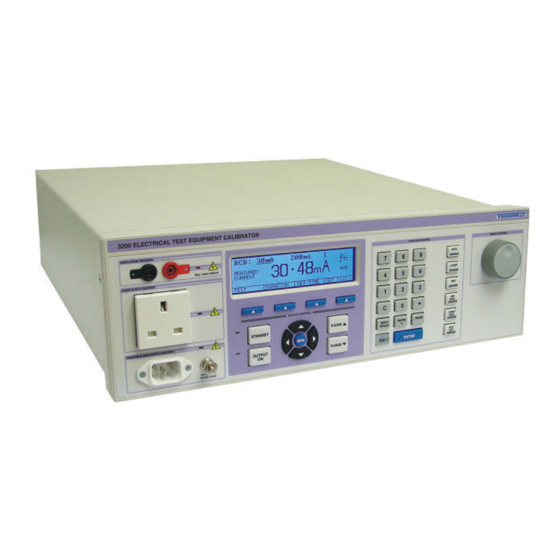
3200A SERIES OPERATION MANUAL 3200A Electrical Test Equipment Calibrator Introduction The 3200 Electrical Test Equipment Calibrator is a breakthrough in electrical test equipment calibration providing a complete solution for testing: Insulation Testers RCD Testers LOOP Testers Portable Appliance Testers (PATs) -
Page 7: Installation & Power Requirements For The 3200A
3200A SERIES OPERATION MANUAL Installation & Power Requirements for the 3200A It is necessary that for correct operation the Phase (Live) and Phase (Neutral) MUST be connected correctly (some plugs used in non-UK countries can be connected either way round, therefore this check will be necessary). There should only be a small voltage between Phase (Neutral) and Phase (Earth). - Page 8 Designed for use in the laboratory or portable on-site calibration. The 3200A calibrator is suitable for use in the standards laboratory. The fast warm up time combined with the small case and low weight make the 3200A series calibrator also ideal for onsite calibration. The serial interface allows direct connection to a PC/laptop.
-
Page 9: Preparing The Calibrator For Use
3200A SERIES OPERATION MANUAL Preparing the calibrator for use. Initial Inspection. After shipment the calibrator should be inspected for any signs of external damage. Should external damage be found contact the carrier immediately. Do not connect a damaged instrument to the line power as this may result in internal damage. Please retain the original packaging;... -
Page 10: Positioning The Calibrator
3200A SERIES OPERATION MANUAL Positioning the Calibrator. The calibrator can be used free standing on a bench or mounted in a standard 19” rack enclosure. The calibrator can be operated at any angle; the two front feet have tilt legs for bench operation. -
Page 11: Rear Panel Connections And Controls
3200A SERIES OPERATION MANUAL Rear Panel Connections and Controls Connections on the rear panel consist of a 9 Pin Serial interface connector for the computer interface; this is optically isolated from the calibrator outputs. Fuse holders for individual instrument functions are accessible from the back of the calibrator. -
Page 12: Setting And Checking The Line Voltage
3200A SERIES OPERATION MANUAL Setting and Checking the Line Voltage. Warning The line power cord must have an earth conductor to avoid the risk of shock. This instrument must be correctly earthed. The calibrator has been designed to work from either 100-120 Volt line supply or 200 - 240 Volt line supply. -
Page 13: Connecting To A Computer
3200A SERIES OPERATION MANUAL Connecting to a computer A USB cable (supplied) should be used to connect the calibrator to a USB port on the PC. Connection Details Connection from calibrator to PC : Also supplied is a USB driver on CD : For details on installing USB driver see appendix A. -
Page 14: Powering Up The Calibrator
3200A SERIES OPERATION MANUAL Powering up the calibrator After connecting line power, the calibrator can be switched on with the line power switch on the rear panel. The front panel display will illuminate indicating power. The display will show program version number and after a short delay, during which time the processor... -
Page 15: Output Connections
3200A SERIES OPERATION MANUAL Output Connections Warning - Risk of shock. High voltages may be present on the output sockets. Output sockets comprise of the following types: IEC 3-Pin Socket: For use with the supplied PAT test lead. 13A Socket (UK)*:... -
Page 16: Operation
3200A SERIES OPERATION MANUAL Operation SAFETY WARNINGS This instrument is capable of generating high voltages WARNING The information in this section is intended only for qualified personnel. The user must at all times be adequately protected from electric shock. Qualified personnel must ensure that operators of the equipment are adequately insulated from connection points. -
Page 17: Front Panel Keyboard
3200A SERIES OPERATION MANUAL Front Panel Keyboard The front panel of the 3200A Calibrator utilises a high quality custom rubber keyboard with tactile feel buttons and integral display window. The front panel is therefore sealed against the ingress of moisture and dirt enabling the calibrator to be used in most working environments without risk of early failure of the operating buttons. -
Page 18: Graphic Lcd Display
3200A SERIES OPERATION MANUAL The Keyboard is divided into sections to allow rapid operation. The Numeric section allowing values to be entered, Functions keys for RCD, LOOP, PAT, Insulation Resistance, Continuity Resistance and ACV Output Range up and range down keys allows range changing for the currently selected function Left/right arrow keys select the digit to be controlled by the digital control knob. -
Page 19: Using The Digital Control
3200A SERIES OPERATION MANUAL Using the Digital Control A digital potentiometer allows the ‘highlighted digit’ on the display to be incremented (turning clockwise) or decrement (turning anti-clockwise). Selected digit marker. Cursor Keys can be used to move the position of the digit marker, and increment / decrement the digit. -
Page 20: Terminal Status Leds
3200A SERIES OPERATION MANUAL Terminal status LEDs LED’s above the terminals indicate the active input / output. Active terminals indicated by illuminated LED PAT Test IEC Socket WARNING Dangerous voltage may be present on these terminals. LOOP & RCD TEST Socket WARNING Dangerous voltage may be present on these terminals. -
Page 21: Calibrating Instruments Using The 3200A
3200A SERIES OPERATION MANUAL Calibrating Instruments Using the 3200A Calibrating Insulation Testers The 3200A has six functions for calibrating insulation and continuity testers: 1. Resistance output for insulation testing (0MΩ to 2GΩ, option to 10GΩ) 2. Measurement of insulation test voltage; ranges 50V, 100V, 250V, 500V & 1000V 3. -
Page 22: Measuring Insulation Test Voltages & Current
3200A SERIES OPERATION MANUAL Measuring Insulation Test Voltages & Current Step 1 From the Insulation Resistance menu displayed on the 3200A, select the VOLTAGE function using the soft key. Step 2 Select the required voltage range using either the digital Control or the up / down arrow keys. - Page 23 3200A SERIES OPERATION MANUAL Step 3 Select the required measurement current using the Soft Keys. The default setting for current load is 0.5mA nominal which is the correct load/test current for the 17 Edition equipment - e.g. must be able to supply 0.5mA at the specified test voltage.
- Page 24 3200A SERIES OPERATION MANUAL Highlight the required voltage by using the curser keys and or the digital control and then press the SELECT soft key. If the voltage applied by the tester is less than 30% of the range or the polarity is incorrect, the display will show 0V (note some tester’s ‘positive’...
-
Page 25: Low Value Resistance For Continuity Testing
3200A SERIES OPERATION MANUAL Low Value Resistance for Continuity Testing Step 1 Connect the insulation tester to the Black & Red 4mm sockets Step 2 Select ‘CONT RES’ from the function keys on the 3200A Fixed values Step 3 Select the required resistance in Ω from 20mΩ to 1kΩ... -
Page 26: Voltage Output
3200A SERIES OPERATION MANUAL A.C. Voltage Output Notes on ACV Output To provide the power necessary for some insulation testers, the AC output from the 3200A is derived from transformer tapping’s. The output is unregulated and will vary with line voltage and loading. The actual output voltage at any time is measured and displayed by the 3200A which can be compared to the displayed value on the UUT. -
Page 27: High Voltage Insulation Tester Adapter [Option Exthv]
3200A SERIES OPERATION MANUAL High Voltage Insulation Tester Adapter [OPTION EXTHV] This option allows the testing of Insulation Testers with test voltages of greater than 1kV and an insulation range up to 200GΩ (1TΩ with OPTION 10G fitted). Connect the EXTHV adaptor and insulation tester under test as shown:... -
Page 28: Introduction To Rcd Testers
3200A SERIES OPERATION MANUAL Introduction to RCD Testers Increasingly in modern installations, earth leakage circuit breakers are used to provide protection in addition to conventional fuses and circuit breakers. These devices are referred to by a variety of names including RCD (Residual Current Devices), RCCB (Residual Current Circuit Breaker), ELCB (Earth Leakage Circuit Breaker) and GFI (Ground Fault Interrupt). -
Page 29: Calibrating Rcd Testers Using The 3200A
3200A SERIES OPERATION MANUAL Calibrating RCD Testers using the 3200A The 3200A has two functions which can be used for complete testing of an RCD tester: 1. RCD Current measurement 2. RCD Trip Time measurement Use the socket marked Loop & RCD Testers to perform RCD tests. -
Page 30: Rcd Current Measurements
3200A SERIES OPERATION MANUAL RCD Current Measurements Warning: Mains output is present during RCD testing Some RCD testers may require a settling delay between the application of mains from the 3200A calibrator and pressing of the TEST button on the RCD tester. This may be indicated by a symbol on the display of the RCD tester. - Page 31 3200A SERIES OPERATION MANUAL Step 1 Connect the RCD tester to the LOOP & RCD TESTER socket Step 2 Select ‘RCD’ from the function key section of the 3200A front panel Step 3 Press the soft key I and choose the required current mode as shown...
- Page 32 3200A SERIES OPERATION MANUAL Step 5 Press the soft key TIME, use the range up / range down buttons, digital control or enter the required time via the numeric keypad and press enter. Timing duration Step 6 Press the soft key TEST...
-
Page 33: Rcd Trip Time Measurements
3200A SERIES OPERATION MANUAL RCD Trip Time Measurements Warning: Mains output is present during RCD testing Some RCD testers may require a settling delay between the application of mains from the 3200A calibrator and pressing of the TEST button on the RCD tester. This may be indicated by a symbol on the display of the RCD tester. - Page 34 3200A SERIES OPERATION MANUAL Step 1 Connect the RCD tester to the LOOP & RCD TESTER socket Step 2 Select ‘RCD’ from the function key section of the 3200A front panel Step 3 Press the soft key I and choose the required current mode as shown...
- Page 35 3200A SERIES OPERATION MANUAL Step 5 Press the soft key TIME, use either the range up / range down buttons, digital control or enter the required time via the numeric keypad and press enter. Timing duration Step 6 Press the soft key TEST...
-
Page 36: Calibrating Portable Appliance Testers (Pats)
3200A SERIES OPERATION MANUAL Calibrating Portable Appliance Testers (PATs) The 3200A has six functions which can be used for testing of Portable Appliance Testers (PATs): 1. Earth Bond Resistance measurement 2. Earth Bond Current measurements 3. Insulation testing 4. Load testing 5. - Page 37 3200A SERIES OPERATION MANUAL Step 2 Select ‘PAT’ from the function key section of the 3200 front panel Step 3 Press the soft key BOND RES to select the earth bond resistance measurement. Step 4 Select the required resistance value using either the range up / range down buttons or by incrementing / decrementing the range using the digital control.
-
Page 38: Pat: Earth Bond Current
3200A SERIES OPERATION MANUAL PAT: Earth Bond Current Step 1 Connect the PAT tester to the PAT TEST IEC socket using the test lead supplied. Connect the PAT tester earth lead to the PAT EARTH BOND LEAD terminal on the 3200 using the lead supplied with the PAT. - Page 39 3200A SERIES OPERATION MANUAL Step 5 Press the soft key SET LOAD to set the load presented to the PAT under test of 0.1Ω or 20mΩ. Load impedance setting Step 6 Press the soft key TEST to allow the 3200A to begin detecting the PAT output current.
-
Page 40: Pat: Insulation Testing
3200A SERIES OPERATION MANUAL PAT: Insulation Testing Step 1 Connect the PAT tester to the PAT TEST IEC socket. Step 2 Select ‘PAT’ from the function key section of the 3200A front panel Step 3 Press the soft key INS RES to select insulation resistance testing. -
Page 41: Pat : Load Testing
3200A SERIES OPERATION MANUAL PAT : Load Testing Step 1 Connect the PAT tester to the PAT TEST IEC socket. Step 2 Select ‘PAT’ from the function key section of the 3200A front panel Step 3 Press the soft key NEXT from the PAT Menu screen... - Page 42 3200A SERIES OPERATION MANUAL Step 5 Press the soft keys beneath the on-screen PAT Load Test menu to select the required mode: Applies a load of 0.13kVA between live and neutral of the PAT under test. Applies a short circuit between live and neutral of the PAT under test.
-
Page 43: Pat : Flash Testing [Option]
3200A SERIES OPERATION MANUAL PAT : Flash Testing [OPTION] The PAT Flash testing mode is an option which requires use of the PAT Flash adapter pod. Step 1 Connect the PAT Flash test adapter to the 3200A back panel socket. - Page 44 3200A SERIES OPERATION MANUAL Step 6 Press the soft keys CLASS 1 and CLASS 2 to select the required flash test mode either 1.5kV (class 1) or 3kV (class 2) The ‘FLASH’ Voltage generated by the PAT under test can either be measured under a nominal 1mA load or measured as the ‘open circuit’...
-
Page 45: Pat: Leakage
3200A SERIES OPERATION MANUAL PAT: Leakage Step 1 Connect the PAT tester to the PAT TEST IEC socket using using the test lead supplied. Step 2 Select ‘PAT’ from the function key section of the 3200A front panel Step 3... -
Page 46: Introduction To Loop Testers
3200A SERIES OPERATION MANUAL Introduction to LOOP Testers What is the loop? When an appliance is connected to the mains supply a circuit is made. It completes the loop current flow round the circuit loop from the power station in the live wire through the appliance and then back to the power station in the neutral wire. - Page 47 3200A SERIES OPERATION MANUAL It can be seen that the maximum current that could flow would be 230 Amps even if the appliance was a dead short circuit. A fuse or protection device lower than 230 amps would be needed to protect this circuit. It should be noted that some testers take the lowest loop, either live/neutral or live/phase to calculate the PSCC while others will use only the live/earth loop resistance.
- Page 48 3200A SERIES OPERATION MANUAL What happens on an RCD protected circuit when using a loop tester? As the test current (23A) flows down the earth conductor any current RCD (Residual current breaker) in the circuit will trip out. To test loop impedance on protected circuits the breaker must either be temporally wired out or a loop tester with a no trip range must be used.
- Page 49 3200A SERIES OPERATION MANUAL IMPORTANT SAFETY WARNING THE FOLLOWING PROCEDURE MAKES CONNECTION DIRECTLY TO MAINS LINE VOLTAGES WHICH ARE UNPROTECTED BY AN RCD BREAKER - THERE IS EXTREME RISK OF ELECTRIC SHOCK UNLESS PROPER SAFETY PRECAUTIONS ARE TAKEN. THIS PROCEDURE MUST ONLY BE PERFORMED BY QUALIFIED ENGINEERS.
- Page 50 3200A SERIES OPERATION MANUAL When using the 3200A it is important to remember the test socket is the socket at the end of the adapter cable, NOT THE RESISTANCE OF THE SOCKET INTO WHICH THE 3200A IS PLUGGED. The loop value measured at this test socket can then be manually entered into the 3200A which will add this value to the calibrated values.
- Page 51 3200A SERIES OPERATION MANUAL The lowest value will be obtained near where the supply enters the building. Remember every switch, fuse socket; even the 3200A will add resistance. If it is required to calibrate at values below that available from of the 3200A then a short length of extension cable of which the resistance of the live + earth conductors have been measured by a 4 wire DMM can be used.
-
Page 52: Calibrating Loop Testers Using The 3200A
3200A SERIES OPERATION MANUAL Calibrating LOOP Testers using the 3200A Loop testing using the 3200A is performed using a fixed set of resistance ranges, with auto (optional extra) and manual loop measurement. Auto Loop Measurement NOTE: Auto loop measurement is an option specified when a 3200A is ordered. - Page 53 3200A SERIES OPERATION MANUAL Use the socket marked Loop & RCD Testers to perform RCD tests. When the TEST soft key is pressed on the 3200A front panel, the 3200A pre-tests the LOOP tester to detect faulty devices. Should a faulty device be detected the output will be automatically switched off and a fault message will be displayed on the 3200A display.
- Page 54 3200A SERIES OPERATION MANUAL Step 5 Press the TEST soft key on the 3200A to apply mains to the LOOP tester Step 6 Press the TEST button on the LOOP tester to begin testing. Step 7 Read the loop resistance from the display of the LOOP tester.
-
Page 55: Pscc (Prospective Short Circuit Current) Testing
3200A SERIES OPERATION MANUAL PSCC (Prospective Short Circuit Current) Testing Some LOOP / Installation testers have the capability to measure PSCC (Prospective Short Circuit Current) which is the largest Prospective Fault Current (PFC) which could flow. This current is limited by the LOOP resistance of the circuit and can be calculated for either: •... -
Page 56: Introduction To Breakdown / Hipot Testers
3200A SERIES OPERATION MANUAL Introduction to Breakdown / Hipot Testers Breakdown / Hipot testers come in various configurations, from a simple AC high voltage source (which is generated by a step up transformer) to more complex units which generate both AC and DC voltages with leakage current measurement capabilities. -
Page 57: Calibrating Breakdown / Hipot Testers Using The 3200A & 2102 Adapter [Option]
3200A SERIES OPERATION MANUAL Calibrating BREAKDOWN / HIPOT Testers using the 3200A & 2102 adapter [OPTION] The Breakdown / Hipot tester testing mode is an option which requires use of the 2102 Breakdown / Hipot Calibration Adaptor. Step 1 Connect the 2102 adapter to the 3200A back panel socket. - Page 58 3200A SERIES OPERATION MANUAL Step 4 Select the voltage range using the soft keys 3kV or 12kV and also either A.C. or D.C. with the AC/DC soft key 3kV AC range selected Step 5 Adjust the output of the breakdown / hipot tester to the required output voltage and read the voltage on the 3200A.
- Page 59 3200A SERIES OPERATION MANUAL Step 7 Increase the output of the instrument under test to set the output current and measure the recorded current on the 3200A. Note: the peak current is also recorded, this can be used to measure The trip current of the instrument under test.
-
Page 60: Remote Programming
3200A SERIES OPERATION MANUAL Remote Programming USB Interface The calibrator can be fully controlled and calibrated via USB interface. The interface is optically isolated from the calibrator circuitry. The calibrator can send information with reference to the output status, calibration factors and value of internal standards together with other information. - Page 61 3200A SERIES OPERATION MANUAL Insulation Tests: Function Command Description INSULATION TESTING Select the insulation function Sxxxx.xx Set resistance value in MΩ, ranges 0Ω to 2GΩ (2000MΩ) – in 10kΩ steps 0Ω to 10GΩ (10000MΩ) – in 10kΩ steps with 10GΩ...
- Page 62 3200A SERIES OPERATION MANUAL A.C. Output: Function Command Description INSULATION TESTER Select the insulation tester voltage VOLTAGE MEASURE measurement function (A.C. output) (A.C.) Set 100V range Set 200V range Set 240V range Set 300V range Set 400V range Transmit output value in 100mV units.
- Page 63 3200A SERIES OPERATION MANUAL Function Command Description PAT : EARTH BOND Select the insulation tester voltage RESISTANCE measurement function Set 0Ω range Set 0.05Ω range Set 0.1Ω range Set 0.22Ω range Set 0.33Ω range Set 0.5Ω range Set 1Ω range Set 5Ωrange...
- Page 64 3200A SERIES OPERATION MANUAL Function Command Description PAT : LOAD TESTING Select the PAT load test function Select 440Ω load between live and neutral Select short circuit Select open circuit Set load range e.g. command line: F14/R1>CR PAT load / load range > carriage return test 440Ω...
- Page 65 3200A SERIES OPERATION MANUAL Function Command Description PAT : LEAKAGE Select the PAT leakage testing function TESTING Set 2mA range Set 4.7mA range Set 7.7mA range Transmit measured value in 1uA units. Set leakage current range e.g. command line: F16/R2>CR...
- Page 66 3200A SERIES OPERATION MANUAL Set RCD trip current in mA with multiplier e.g. command line: F85/S100/N2>CR RCD current / current / current > carriage return 100mA multiplier Set RCD trip time in ms and start test e.g. command line: F86/S20/F21>CR...
- Page 67 3200A SERIES OPERATION MANUAL Function Command Description Command 3200A to measure its mains resistance (Auto loop option) Select manual mains resistance menu Sx.xxx Send manual mains resistance in ohms For use in conjunction with F84 command Set loop resistance range e.g.
- Page 68 3200A SERIES OPERATION MANUAL Function Command Description BREAKDOWN TESTER Select the breakdown tester current function CURRENT Set 20mA A.C. range Set 2mA A.C. range Set 200uA A.C. range Set 20mA D.C. range Set 2mA D.C. range Set 200uA D.C. range...
-
Page 69: Technical Description
3200A SERIES OPERATION MANUAL Technical Description General The 3200A calibrator uses the latest in reference, resistor and processor technology designed to minimise cost and size yet maximise performance. The micro processor controls and monitors all functions of the calibrator. Calibration constants are held in non volatile memory allowing the calibration to be performed without removing the covers. -
Page 70: Internal Fuses
3200A SERIES OPERATION MANUAL Internal Fuses. Under normal operating conditions these fuses should not need to be replaced. Only under fault conditions will they require changing. NOTE: To access these fuses it is necessary to dismantle the case which should only be carried out by qualified personnel. -
Page 71: Pcb Removal (Not Required To Gain Access To Internal Fuses)
3200A SERIES OPERATION MANUAL PCB Removal (Not required to gain access to internal fuses). The main PCB can only be removed from the front of the case by removing the front panel. Processor Board Plugs into the main PCB and controls all functions within the calibrator. The processor also manages all calibration constants held in memory. -
Page 72: Calibration And Maintenance
3200A SERIES OPERATION MANUAL Calibration and Maintenance WARNING The information in this section is intended only for qualified personnel. The user must at all times be adequately protected from electric shock. General The 3200A calibrator maintenance requirements are listed below. Please note that the calibrator does not require any regular internal servicing or adjustment. - Page 73 Adjustments to the calibration can only be made using the interface see remote commands section of this manual for details. A Calibration Control Panel (CCP) program is available from Transmille which allows full control and adjustment of the calibrator. The recalibration of 3200A calibrator should be performed annually in a standards laboratory with the correct equipment.
-
Page 74: Guarantee And Service
To obtain repair under this guarantee the purchaser must send the instrument (carriage prepaid) and a description of the fault to Transmille at the address shown below. The instrument will be repaired at the factory and returned to the purchaser, carriage prepaid. - Page 75 +44 (0) 1580 890711. Please Fax This Form To : On receipt of this fax Transmille will, on receipt of payment for the calibrator, send details of the security code with details on how to enter this code. TRANSMILLE LTD.
-
Page 76: Installing The Usb Interface Driver (Windows Xp)
3200A SERIES OPERATION MANUAL Appendix A Installing the USB Interface Driver (Windows XP) Insert the supplied USB lead driver CD into the computer CD drive Click on menu to install driver – follow on screen prompts. Connect the USB lead to the INSTRUMENT and connect to the computer... -
Page 77: Installing The Usb Interface Driver (Windows Vista / 7)
3200A SERIES OPERATION MANUAL Installing the USB Interface Driver (Windows Vista / 7) Insert the supplied USB lead driver CD into the computer CD drive Click on menu to install driver – follow on screen prompts. Connect the USB lead to the INSTRUMENT and connect to the computer... -
Page 78: Checking The Com Port Setting For The Usb Interface
3200A SERIES OPERATION MANUAL Checking the COM Port setting for the USB Interface Once the USB interface driver is installed, it will have assigned a ‘virtual’ COM port number which is needed for setting up the instrument for computer control (via optional ProCal Calibration software).
Need help?
Do you have a question about the 3200A Series and is the answer not in the manual?
Questions and answers