Table of Contents
Advertisement
Available languages
Available languages
Quick Links
I
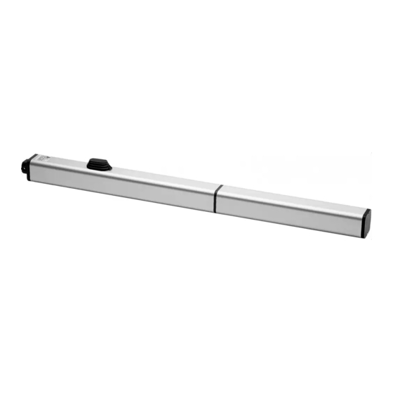
AUTOMAZIONI A PISTONE PER CANCELLI A BATTENTE
GB
PISTON AUTOMATION FOR SWING GATES
ISTRUZIONI D'USO E DI INSTALLAZIONE
INSTALLATION AND USER'S MANUAL
Via Lago di Vico, 44
36015 Schio (VI)
Tel.naz. 0445 696511
Tel.int. +39 0445 696533
Fax 0445 696522
Internet: www.bft.it
E-mail: sales@bft.it
D811293 ver. 02 14-02-03
8 0 2 7 9 0 8 1 7 1 5 5 9
P7 - P 4.5
Advertisement
Table of Contents

Subscribe to Our Youtube Channel
Related Manuals for BFT P7 - P 4.5


Summary of Contents for BFT P7 - P 4.5
- Page 1 AUTOMAZIONI A PISTONE PER CANCELLI A BATTENTE PISTON AUTOMATION FOR SWING GATES 8 0 2 7 9 0 8 1 7 1 5 5 9 P7 - P 4.5 ISTRUZIONI D'USO E DI INSTALLAZIONE INSTALLATION AND USER'S MANUAL Via Lago di Vico, 44 36015 Schio (VI) Tel.naz.
- Page 2 P7 - P4.5 Ver. 02...
- Page 3 MANUALE D’USO ITALIANO Nel ringraziarVi per la preferenza accordata a questo prodotto, la ditta è certa che da esso otterrete le prestazioni necessarie al Vostro uso. Leggete attentamente l’opuscolo “Avvertenze” ed il “Libretto istruzioni” che accompagnano questo prodotto in quanto forniscono importanti indicazioni riguardanti la sicurezza, l’installazione, l’uso e la manutenzione.
-
Page 4: General Outline
USER’S MANUAL ENGLISH Thank you for buying this product, our company is sure that you will be more than satisfied with the product’s performance. The product is supplied with a “Warnings” leaflet and an “Instruction booklet”. These should both be read carefully as they provide important information about safety, installation, operation and maintenance. - Page 5 MANUALE PER L’INSTALLAZIONE ITALIANO Nel ringraziarVi per la preferenza accordata a questo prodotto, la ditta è l’apertura e la chiusura, al fine di ridurre il rischio di intrappolamento. certa che da esso otterrete le prestazioni necessarie al Vostro uso. I cancelli a battente non potranno essere aperti in aree di pubblico Leggete attentamente l’opuscolo “Avvertenze”...
- Page 6 ITALIANO MANUALE PER L’INSTALLAZIONE cato. Forcella anteriore di fissaggio dell’anta. • L’entrata è riservata ai veicoli. Prevedere un’entrata separata per i Quote per determinare il punto di fissaggio della staffa ”P”. pedoni. Valore dell’interasse di fissaggio. • Conservare le presenti istruzioni. Lunghezza dell’anta.
-
Page 7: Manutenzione
MANUALE PER L’INSTALLAZIONE ITALIANO fissata con viti adeguate (fig.12c). 10) REGOLAZIONE DELLA FORZA DI SPINTA • Se il cancello è di legno, la forcella può essere fissata con viti adeguate Per motivi di sicurezza per accedere alle valvole di regolazione bisogna (fig.12b). -
Page 8: Inconvenienti E Rimedi
ITALIANO MANUALE PER L’INSTALLAZIONE 16) INCONVENIENTI E RIMEDI 16.1) Funzionamento difettoso dell’attuatore Verificare con apposito strumento la presenza di tensione ai capi dell’attuatore dopo il comando di apertura o chiusura. Se il motore vibra ma non gira, può essere: • Sbagliato il collegamento del filo comune C, (in ogni caso è... - Page 9 INSTALLATION MANUAL ENGLISH Thank you for buying this product, our company is sure that you will be more FOR GATE OPENERS WITH HOLD-TO-RUN CONTROL: than satisfied with the product’s performance. The product is supplied with • The gate operator controls must be placed so that the user has full view a “Warnings”...
-
Page 10: Technical Specifications
ENGLISH INSTALLATION MANUAL 3) MAIN AUTOMATION PARTS (Fig.1) during manoeuvring. Maximum “a” and “b” values develop maximum piston 2-pole single-phase motor, protected by thermal circuit-breaker. force. Warning! All versions are provided with a ball joint which allows the Hydraulic lobe pump. rod to be lengthened or shortened by approximately 0.19 in (5 mm), but only Distributor with adjustment valves. -
Page 11: Maintenance
INSTALLATION MANUAL ENGLISH time, and allows the catch to stay lifted when it reaches the closing position, never exceed the limits set out by the current national standards. Under without opposing any resistance; the catch will drop into position when the no circumstances whatsoever must the by-pass valves be fully gate has completed the closing cycle. - Page 12 ENGLISH INSTALLATION MANUAL and bridge all the automation devices one by one, if necessary, until the faulty device is identified. After replacing or repairing it, restore all the devices which were previously disconnected or bridged. For all devices installed, refer to their respective instruction manual. Warning: the above operation must be carried out by qualified personnel.
- Page 13 Fig. 1 Fig. 2 55.82" (1418) 52.55" (1335) 36.41" (925) 16.14" (410) Ct 0.39" 15.35" (390) Cu 0.39" (10) (10) 0.78" Cr Ct = Corsa totale Cu = Corsa utile Cr = Corsa rallentamento (20) Cr Total stroke Working stroke Slow-down stroke The values between brackets are expressed in millimetres Fig.
- Page 14 Fig. 4 αϒ Fig. 5 Fig. 6 2.16" (55) Fig. 7 Fig. 8 14 - P7 - P4.5 Ver. 02...
- Page 15 Fig. 9 Fig. 10 7ϒ Fig. 11 Fig. 12 P7 - P4.5 Ver. 02 -...
- Page 16 Fig. 13 Fig. 14 Close 15.74" (400) ( 4 0 7 4 " 1 5 . Open Fig. 15 Fig. 16 18 AWG = 1 mm 16 AWG = 1.5 mm 16 - P7 - P4.5 Ver. 02...
- Page 17 Fig. 17 Fig. 18 Fig. 19 CLOSE OPEN P7 - P4.5 Ver. 02 -...
- Page 18 Fig. 20 Fig. 21 Fig. 22 18 - P7 - P4.5 Ver. 02...
- Page 19 P7 - P4.5 Ver. 02 -...
- Page 20 BFT S.p.a. ITALIA Via Lago di Vico, 44 36015 Schio (VI) Tel.naz. 0445 696511 Tel.int. +39 0445 696533 Fax +39 0445 696522 Internet: www.bft.it E-mail: sales@bft.it...
Need help?
Do you have a question about the P7 - P 4.5 and is the answer not in the manual?
Questions and answers