Table of Contents
Advertisement
Quick Links
Advertisement
Table of Contents

Subscribe to Our Youtube Channel
Related Manuals for Wavecom W40PC


Summary of Contents for Wavecom W40PC
- Page 1 WAVECOM Decoders v6.15 W40PC, W41PC, W51PC by WAVECOM Elektronik AG.
- Page 2 Internet: http://www.wavecom.ch © by WAVECOM Elektronik AG. All rights reserved. Reproduction in whole or in part in any form is prohibited without written consent of the copyright owner. The publication of information in this document does not imply freedom from patent or other protective rights of WAVECOM ELEKTRONIK AG or others.
-
Page 3: Table Of Contents
Install & Uninstall Setup W40PC ..........................3 W40PC Hardware Installation..................3 W40PC Software Installation ..................8 W40PC First Time Start, Card Installed..............10 W40PC System and Error Messages ................. 11 W40PC Software Uninstallation ................12 Setup W41PC .......................... 12 W41PC Hardware Installation................... 12 W41PC Software Installation .................. - Page 4 VHF REAL-TIME FFT DIRECT (W51PC, W40PC)..........74 FFT & SONAGRAM ......................74 HF FFT & SONAGRAM ..................75 VHF FFT & SONAGRAM INDIRECT (W51PC, W40PC) ........75 VHF FFT & SONAGRAM DIRECT (W51PC, W40PC) ......... 75 REAL-TIME WATERFALL....................75 HF REAL-TIME WATERFALL ................76 VHF REAL-TIME WATERFALL INDIRECT (W51PC, W40PC) ......
- Page 5 VHF FSK ANALYSIS DIRECT (W51PC, W40PC)..........83 CODE CHECK........................84 HF FSK CODE CHECK ................... 84 VHF FSK CODE CHECK INDIRECT (W51PC, W40PC) ........86 VHF FSK CODE CHECK DIRECT (W51PC, W40PC) .......... 87 PSK SYMBOL RATE and PSK PHASE PLANE..............88 MFSK ANALYSIS........................
- Page 6 PACKET-9600 ........................168 PACTOR ..........................169 PACTOR-II ........................... 169 Tuning a PACTOR-II Signal with W41PC ............. 170 Tuning a PACTOR-II Signal with W51PC or W40PC ........... 171 PICCOLO-MK6 and PICCOLO-MK12 ................172 POCSAG ..........................174 POL-ARQ..........................175 PRESS-FAX .......................... 176 PSK-31...........................
- Page 7 Tuning a PSK-31 Signal with W51PC or W40PC ..........178 Polarity of PSK-31 ....................179 PSK-63F and PSK-125F......................179 Tuning a PSK-63F and PSK-125F Signal with W41PC.......... 180 Tuning a PSK-63F and PSK-125F Signal with W51PC or W40PC......181 RUM-FEC ..........................182 SI-ARQ..........................183 SI-FEC ........................... 183 SI-AUTO ..........................
- Page 8 W51PC 6.0 ......................242 2004, March........................... 242 W51PC 6.1 ......................242 W41PC 5.6 ......................243 Missing ........................243 2004, Sept ..........................243 W51PC ........................243 W40PC ........................244 Glossary of Terms Index viii • Contents WAVECOM Decoders v6.15 W40PC, W41PC, W51PC...
-
Page 9: Welcome
Always check the newest documentation on the CD or on our homepage. We thank you for choosing a WAVECOM decoder and look forward to work for you in the future. This chapter introduces you to what WAVECOM is and what it does and what you might use it for. Professional Version Please register your software if you are a professional user (governmental bodies), otherwise we can not send you the professional version of the software and inform you about updates. - Page 10 About 40% of the turnover is invested in research and development. The employees at WAVECOM ELEKTRONIK AG are mainly engineers with a lot of experience in DSP technology, computer and RF hardware development, software engineering and radio data transmission.
-
Page 11: Install & Uninstall
W40PC I/O Address Settings PC Note: The W40PC hardware only requires an address range in the I/O address space of the PC. No DMA (Direct Memory Access) or IRQ (Interrupt) channels are required. As one PC at the maximum accommodates one W40PC card, automatic installation (Plug-and- Play, PnP) is presently not available. - Page 12 • Select the "I/O Port" button to display the allocated I/O resources. Note: If the W40PC application is running, the I/O space assigned to the W40PC would also be displayed in the list. 4 • Install & Uninstall WAVECOM Decoders v6.15 W40PC, W41PC, W51PC...
- Page 13 The default I/O address of 0310 is not occupied, and is free to use for the W40PC installation. Procedure for WINDOWS 2000: • Right click on the "My Computer" icon on the desktop. • Select the "Properties" Menu Item to open the "System Properties"...
- Page 14 W40PC I/O Address Selection Card The selection of the W40PC I/O address is controlled by two jumpers on the card, JP1 and JP2. The factory default setting is 0310 hexadecimal with JP1 installed. Next to the jumpers a table with valid address values is printed.
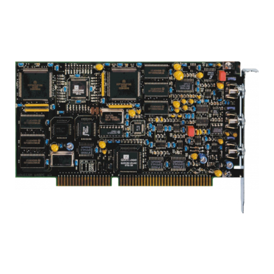
- Page 15 W40PC Card Installation Before unpacking the W40PC card or installing it in your PC be sure you are grounded to avoid damaging static-sensitive components on the card or in the computer. You can reduce static electricity on your person by touching the metal chassis of your computer.
-
Page 16: W40Pc Software Installation
-12V/0.5 A. W40PC Software Installation The W40PC and other software is contained on a CD-ROM. The installation is very easy and complies with standard WINDOWS installation procedures. Place the CD in the CD-ROM drive. Usually the installation program should start automati- cally. - Page 17 When the installation is completed, the W40PC program may be started even without the hardware being installed. Click on "W40PC" to make a test start. A start of a transmission mode is not possible without W40PC hardware, however.
-
Page 18: W40Pc First Time Start, Card Installed
Note: It is only possible to run and install one W40PC-card in the same PC at the same time. W40PC First Time Start, Card Installed If the I/O address is missing after program start the following message is displayed: First time the W40PC software is started with the W40PC card installed, the software must be informed of the address configuration of the W40PC card. -
Page 19: W40Pc System And Error Messages
W40PC System and Error Messages If the I/O address is missing after program start, the following message is displayed: If the software does not detect any W40PC card the message shown below is displayed. This indicates that the installation procedure has not been correct. -
Page 20: W40Pc Software Uninstallation
Choose "W40PC" from the displayed list • Click on "ADD/REMOVE" Now the software has been removed from the PC. It is possible, that the W40PC icons have to be manually removed. Setup W41PC The powerful W41PC hardware utilizes two Digital Signal Processors (DSP) and one 16/32 bit processor. - Page 21 The selection of the W41PC I/O address is controlled by three jumpers on the card, JP1, JP2 and JP3. The factory default setting is 310 hexadecimal with JP2 and JP3 installed. Install & Uninstall • 13 WAVECOM Decoders v6.15 W40PC, W41PC, W51PC...
- Page 22 W41PC Connecting to a W41PC Card The W41PC card has three BNC signal inputs available: Note: The W41PC MK-II hardware utilizes four signal inputs, i.e. an EXT-DEM (EXTernal DEModulator) input is additionally available. 14 • Install & Uninstall WAVECOM Decoders v6.15 W40PC, W41PC, W51PC...
-
Page 23: W41Pc Software Installation
By starting the software installation, the old version will automatically be uninstalled. After that process has finished, you may install the new software release. Therefore you have to restart the installation program manually. Install & Uninstall • 15 WAVECOM Decoders v6.15 W40PC, W41PC, W51PC... - Page 24 Clicking on "Next" continues the installation. The W41PC default software directory is "\Program Files\WAVECOM\W41PC", but if required the directory may be changed. After a new click on "Next" the dialog box asks for a folder name for the start menu. The default is called "WAVECOM\W41PC".
-
Page 25: W41Pc First Time Start, Card Installed
The W41PC uses Microsoft DCOM to communicate between the W41PC card (W41PC server) and the user interface (W41PC client). Microsoft DCOM allows the client and server to be separated by a network, thus enabling remote control. Install & Uninstall • 17 WAVECOM Decoders v6.15 W40PC, W41PC, W51PC... -
Page 26: W41Pc System And Error Messages
Installation is now completed and the W41PC is ready for use. From the "HF-Modes" or "VHF-UHF-Modes" menus a mode may be selected. W41PC System and Error Messages If the I/O address is missing after program start, the following message is displayed: 18 • Install & Uninstall WAVECOM Decoders v6.15 W40PC, W41PC, W51PC... -
Page 27: W41Pc Software Uninstallation
Click on "START", go to the "SETTINGS" menu and open "CONTROL PANEL" • Select the icon "ADD/REMOVE PROGRAMS" • Select "INSTALL/UNINSTALL" • Choose "W41PC" from the displayed list • Click on "ADD/REMOVE" Install & Uninstall • 19 WAVECOM Decoders v6.15 W40PC, W41PC, W51PC... -
Page 28: Setup W41Usb
VHF-UHF scanner to the 10.7 MHz IN connector. To avoid distortion of the input signal the input voltage range above should be observed. Below is an example of how to connect a W41USB: 20 • Install & Uninstall WAVECOM Decoders v6.15 W40PC, W41PC, W51PC... - Page 29 If you use your own power supply first check the polarity ('+' positive, on the center pin) and the output voltage (11-16.5V @ 1 A), otherwise you may damage your decoder. Install & Uninstall • 21 WAVECOM Decoders v6.15 W40PC, W41PC, W51PC...
-
Page 30: W41Usb Software Installation
Connect your W41USB to the USB port and switch the unit on. • Check if the USB port is properly installed under WINDOWS. • We recommend that you uninstall other WAVECOM software. • The software is contained on a CD-ROM. The installation is very easy and complies with standard WINDOWS installation procedures. - Page 31 CD-ROM (for this it has still to be placed in the drive). If manual installation is required you can do that from the driver directory on the WAVECOM When the installation is completed, the program may be started even without the hardware being installed.
-
Page 32: W41Usb First Time Start
When the driver is installed, the you should see a picture like this in the device manager. W41USB First Time Start 24 • Install & Uninstall WAVECOM Decoders v6.15 W40PC, W41PC, W51PC... - Page 33 The LED "DSP Function" will switch on, when the DSP is ready. About 5 sec. later the installation is completed and the W41USB is ready for use. Switch to the waterfall mode and you will see a picture like this: Install & Uninstall • 25 WAVECOM Decoders v6.15 W40PC, W41PC, W51PC...
-
Page 34: W41Usb System And Error Messages
Click on "START", go to the "SETTINGS" menu and open "CONTROL PANEL" • Select the icon "ADD/REMOVE PROGRAMS" • Select "INSTALL/UNINSTALL" • Choose "W41USB" from the displayed list • Click on "ADD/REMOVE" 26 • Install & Uninstall WAVECOM Decoders v6.15 W40PC, W41PC, W51PC... -
Page 35: Setup W51Pc
The DSP demodulate the incoming data while the PC CPU does the decoding and finally the display of the data. One PC can accommodate a maximum of eight W51PC cards. WAVECOM recommends to use not more than four cards in a standard PC. -
Page 36: W51Pc Software Installation
Before installing a new software update, the old version must be uninstalled (see Software Uninstallation) The software is contained on a CD-ROM. The installation is very easy and complies with standard WINDOWS installation procedures. 28 • Install & Uninstall WAVECOM Decoders v6.15 W40PC, W41PC, W51PC... - Page 37 Otherwise it can be started with the "WINDOWS Explorer" by double-clicking "Installation.exe". Now the welcome-dialog of the installation program is shown: Clicking on W51PC V6.0.00 start the installation of the W51PC software. Install & Uninstall • 29 WAVECOM Decoders v6.15 W40PC, W41PC, W51PC...
- Page 38 Select the number of W51PC cards you have in this computer. Clicking on "Next" continues the installation. The W51PC default software directory is "\Program Files\WAVECOM\W51PC", but if required the directory may be changed. Click on the Next button to select the Setup Type.
- Page 39 • Typical • Compact • Custome If you plan to use third party remote control software, select Custom. On the next scrren enable DCOM Interface and DCOM Server Control. Install & Uninstall • 31 WAVECOM Decoders v6.15 W40PC, W41PC, W51PC...
-
Page 40: W51Pc First Time Start, Card Installed
W51PC First Time Start, Card Installed The software must be informed of the location of the W51PC card. Clicking on "W51PC Card" in the "Setup" menu will display the dialog box shown below. 32 • Install & Uninstall WAVECOM Decoders v6.15 W40PC, W41PC, W51PC... - Page 41 Remote Computer Name or IP Address • TCP Port. Enter the port your server is listening. The default value for the WAVECOM server is 33133. Your client can only connect to the server if they are working on the same port. •...
-
Page 42: W51Pc Command Line Parameters
The following commands are accepted: /i inifilename The name of the ini file located in the same directory as the W51PC. Additionally also a path can be used. /n cardnumber 34 • Install & Uninstall WAVECOM Decoders v6.15 W40PC, W41PC, W51PC... -
Page 43: W51Pc System And Error Messages
Computer Name or the IP address plus the port number to connect another computer . The port number must be setup on the WAVECOM Server Control screen. If no port number is added, then the default port 33133 is used. -
Page 44: W51Pc Software Uninstallation
Now the software has been removed from the PC. It is possible, that the icons may have to be manually removed. Setup W51LAN W51LAN Hardware Setup With the W51LAN you get the following parts from WAVECOM: • a standard W51PC (build into the single board computer) •... -
Page 45: W51Lan Remote Mode (Dcom Required)
(W51LANxxxx). Enter the port (default 33133) and select on speed (10M for LAN) • Search for the card. • Select the card and close the setup window. • Start a mode Install & Uninstall • 37 WAVECOM Decoders v6.15 W40PC, W41PC, W51PC... -
Page 46: W51Lan Remote Desktop Operation (Dcom Not Required)
Connect the W51LAN to the LAN. • Check if you can see the W51LAN computer on your LAN • Start the "Remote Desktop Connection" (Start - All Programs – Accessories - Communications" 38 • Install & Uninstall WAVECOM Decoders v6.15 W40PC, W41PC, W51PC... - Page 47 It safes you a lot of time if you place a direct link to the Remote Desktop Connection on the desktop Install & Uninstall • 39 WAVECOM Decoders v6.15 W40PC, W41PC, W51PC...
- Page 48 When you are connected, then the W51LAN computer will be represented by its own window on your client computer. You start now the W51PC on the W51LAN system. You can also use this mode for software updates. 40 • Install & Uninstall WAVECOM Decoders v6.15 W40PC, W41PC, W51PC...
-
Page 49: W51Lan With Third Party Software (Dcom Required)
Connect a monitor, keyboard and mouse to the W51LAN. For software updates you can connect a USB-CD ROM to the USB connector ion front of the unit.. Hyper-Threading Currently Hyper-Threading is not yet supported by WAVECOM decoders. If you have problems, then disable it. DCOM configuration for firewalls... -
Page 50: Restricting The Range Of Tcp Ports
Ports range(s) specified above. • If you are using callbacks, permit incoming traffic on all ports where the TCP connection was initiated by your server. 42 • Install & Uninstall WAVECOM Decoders v6.15 W40PC, W41PC, W51PC... -
Page 51: General Operating Procedure
General Operating Procedure The pictures in this manual are take from W51PC, W41PC and W40PC screenshots. As not all software versions are completely identical minor differences must be accepted. Using the Decoder This chapter will tell you : • How to start and set up your software •... -
Page 52: Setup
Setup The user interface of the WAVECOM decoder software conforms to standard WINDOWS interface guidelines. A full window is shown below. This is the window you will see after setup has been completed as described in the preceding paragraph. The first time the software is used after installation, you will have to set the decoder card manually. -
Page 53: User Interface (Mmi)
Using the "Files" menu, files may be saved and opened. In addition printing, preview and printer setup is available. For context sensitive help on a menu item, use F1 on the item. General Operating Procedure • 45 WAVECOM Decoders v6.15 W40PC, W41PC, W51PC... -
Page 54: View Menu
"Menu". To start a mode click on the appropriate menu field. Leaving the full-screen menu will not terminate an active mode. 46 • General Operating Procedure WAVECOM Decoders v6.15 W40PC, W41PC, W51PC... -
Page 55: Decoder And Analysis Full Screen Menu
To facilitate an overview, a full-screen menu may be opened by clicking the menu item "Menu". To start an analysis tool click on the appropriate menu field. Leaving the full-screen menu will not terminate an active analysis tool. General Operating Procedure • 47 WAVECOM Decoders v6.15 W40PC, W41PC, W51PC... - Page 56 48 • General Operating Procedure WAVECOM Decoders v6.15 W40PC, W41PC, W51PC...
-
Page 57: Demodulator Menu
For speeds above 300 Baud the DSP-demodulator should be selected. Most VHF-UHF modes features a pre-selected demodulator mode for optimum performance. Input The decoder has different kinds of inputs availble: General Operating Procedure • 49 WAVECOM Decoders v6.15 W40PC, W41PC, W51PC... - Page 58 IF is common for VHF-UHF receivers. • The DIS input (Discriminator) on the W40PC has a range of 0 – 20 kHz. This input is supported by a few VHF-UHF receivers and facilitates the reception of ”Direct FSK” signals like POCSAG or PACKET-9600.
- Page 59 In the following phase comparator the phase difference is calculated from the integrator and the delayed signal. DPSK is almost exclusively used for short wave data links. BPSK General Operating Procedure • 51 WAVECOM Decoders v6.15 W40PC, W41PC, W51PC...
-
Page 60: Options Menu
Latin, Greek, Cyrillic, Hebrew , Arabic etc. ASCII characters for German, Bulgarian, US, Swedish,Danish-Norwegian, Chinese etc. output may be selected too. Skyper, an alphabet which is used in POCSAG mode in Germany, is also available. 52 • General Operating Procedure WAVECOM Decoders v6.15 W40PC, W41PC, W51PC... - Page 61 The software will decrease the size of the phase correction steps in accordance with the verified, reduced phase errors, and thus prevent bit glitches and the resulting loss of synchronism. It is therefore recommended to use "IAS” enabled as default. General Operating Procedure • 53 WAVECOM Decoders v6.15 W40PC, W41PC, W51PC...
-
Page 62: Favorites Menu
Clears the actual screen. All data will be lost. Resync Mode Forces a new synchronization in the current mode. Favorites Menu It is possible to save and relad a mode with all the settings. 54 • General Operating Procedure WAVECOM Decoders v6.15 W40PC, W41PC, W51PC... - Page 63 • • • … that have been once stored with "Save As…" in a *.wfv file. Save As… With "Save As..." you store all the settings like • Mode General Operating Procedure • 55 WAVECOM Decoders v6.15 W40PC, W41PC, W51PC...
-
Page 64: Setup
Each W51PC card is identified by a unique serial number. Thus the W51PC software is able to search for W51PC cards automatically. This functionality is available for both a local and a remote computer. Pressing the ”Search for Cards” button will start the process. 56 • General Operating Procedure WAVECOM Decoders v6.15 W40PC, W41PC, W51PC... - Page 65 The W51PC system can be used in a network configuration. This allows the system to be controlled remotely . Font As long as a mode is not running the menu item is disabled. General Operating Procedure • 57 WAVECOM Decoders v6.15 W40PC, W41PC, W51PC...
- Page 66 You can select different values for: • Text modes • Fax modes • FSK Analysis 58 • General Operating Procedure WAVECOM Decoders v6.15 W40PC, W41PC, W51PC...
- Page 67 If enabled, the decoder will start again in the last used mode. • When selecting "FFT" and "PSK Symbol Rate" pause graphics while cursors are active. Enable or disable the General Operating Procedure • 59 WAVECOM Decoders v6.15 W40PC, W41PC, W51PC...
-
Page 68: Help
Shows you exact information about the release date, build and the software version. Button Bars The selection of the most important decoder functions is facilitated by toolbar buttons. Operation is identical to the use of the menu bar. 60 • General Operating Procedure WAVECOM Decoders v6.15 W40PC, W41PC, W51PC... -
Page 69: Toolbar
Spectrum Indicator The spectrum is a tuning help. For FSK signals , it shows you MARK and SPACE. For PSK signals the carrier is displayed. General Operating Procedure • 61 WAVECOM Decoders v6.15 W40PC, W41PC, W51PC... -
Page 70: Status Bars
MARK and SPACE are keyed. The two tones should be symmetrically grouped around the center of the tuning indicator. Tuning a Twinplex (F7B) Signal Tuning with MFSK demodulator 62 • General Operating Procedure WAVECOM Decoders v6.15 W40PC, W41PC, W51PC... -
Page 71: Tuning A Cw-Morse Signal
In this case the signal shown is a PICCOLO-MK6 transmission. By tuning the receiver or changing the General Operating Procedure • 63 WAVECOM Decoders v6.15 W40PC, W41PC, W51PC... -
Page 72: Tuning An Ermes Signal
The descriptions of the operating modes which follow, are arranged in alphabetical order. Future extensions and updates can thus be incorporated more easily. Some modes of operation are currently under development and are hence already documented. 64 • General Operating Procedure WAVECOM Decoders v6.15 W40PC, W41PC, W51PC... -
Page 73: Main Menu
Simplex Modes on the HF Menu • FEC Modes on the HF Menu • FSK Modes on the HF Menu • FAX modes on the HF Menu • CIS Modes on the HF Menu General Operating Procedure • 65 WAVECOM Decoders v6.15 W40PC, W41PC, W51PC... -
Page 74: Analysis Modes On The Hf Menu
Analysis Modes on the VHF/UHF Menu • Selcal Analog Modes on the VHF/UHF Menu • Selcal Digital Modes on the VHF/UHF Menu Analysis Modes on the HF Menu Standard Modes on the HF Menu 66 • General Operating Procedure WAVECOM Decoders v6.15 W40PC, W41PC, W51PC... -
Page 75: Duplex Modes On The Hf Menu
Duplex Modes on the HF Menu Simplex Modes on the HF Menu General Operating Procedure • 67 WAVECOM Decoders v6.15 W40PC, W41PC, W51PC... -
Page 76: Fec Modes On The Hf Menu
FEC Modes on the HF Menu MFSK Modes on HF Menu FAX Modes on the HF Menu 68 • General Operating Procedure WAVECOM Decoders v6.15 W40PC, W41PC, W51PC... -
Page 77: Selcal Hf Modes On The Hf Menu
SELCAL HF Modes on the HF Menu Analysis Modes on the VHF/UHF Menu General Operating Procedure • 69 WAVECOM Decoders v6.15 W40PC, W41PC, W51PC... -
Page 78: Selcal Analog Modes On The Vhf/Uhf Menu
Selcal Analog Modes on the VHF/UHF Menu Selcal Digital Modes on the VHF/UHF Menu 70 • General Operating Procedure WAVECOM Decoders v6.15 W40PC, W41PC, W51PC... -
Page 79: Advanced Topics
Advanced Topics General The WAVECOM analysis software may be used for : • the determination of frequency shifts of FSK, F7B or MFSK modulated signal types (FSK Analysis) • the exact determination of the signal baud rate (FSK Analysis) •... - Page 80 When the cursors have been placed in the desired positions they may all be moved right or left by moving the center cursor. The measurement of frequency spacing in MFSK and FDM systems is hence significantly facilitated. 72 • Advanced Topics WAVECOM Decoders v6.15 W40PC, W41PC, W51PC...
-
Page 81: Adjustment Of The Translation Frequency
453.3 kHz to obtain the standard center frequency of 1,700 Hz. The HF-1000 BFO must now be adjusted to 1,700 Hz. Thus it is not necessary to change the Advanced Topics • 73 WAVECOM Decoders v6.15 W40PC, W41PC, W51PC... -
Page 82: Hf Real-Time Fft
"Analysis Buttons" start HF analysis mode" is not enabled. (See Preferences… on page 54) VHF REAL-TIME FFT INDIRECT (W51PC, W40PC) The Analysis is started with the input, gain, translation frequency etc. that was used, last time in a VHF INDIRECT mode. This selection is only available in the menu Preferences… the "When selecting the toolbar "Analysis Buttons"... -
Page 83: Hf Fft & Sonagram
"Analysis Buttons" start HF analysis mode" is not enabled. (See Preferences… on page 54) VHF FFT & SONAGRAM INDIRECT (W51PC, W40PC) The Analysis is started with the input, gain, translation frequency etc. that was used, last time in a VHF INDIRECT mode. This selection is only available in the menu Preferences… the "When selecting the toolbar "Analysis Buttons"... -
Page 84: Hf Real-Time Waterfall
The Analysis is started with the input, gain, translation frequency etc. that was used, last time in a HF mode. This selection is only available in the menu Preferences… the "When selecting the toolbar "Analysis Buttons" start HF analysis mode" is not enabled. (See Preferences… on page 54) 76 • Advanced Topics WAVECOM Decoders v6.15 W40PC, W41PC, W51PC... -
Page 85: Vhf Real-Time Waterfall Indirect (W51Pc, W40Pc)
"When selecting the toolbar "Analysis Buttons" start HF analysis mode" is not enabled. (See Preferences… on page 54) VHF REAL-TIME WATERFALL DIRECT (W51PC, W40PC) The Analysis is started with the input, gain, translation frequency etc. that was used, last time in a VHF DIRECT mode. -
Page 86: Hf Real-Time Sonagram (W51Pc, W40Pc)
"When selecting the toolbar "Analysis Buttons" start HF analysis mode" is not enabled. (See Preferences… on page 54) VHF REAL-TIME SONAGRAM DIRECT (W51PC, W40PC) The Analysis is started with the input, gain, translation frequency etc. that was used, last time in a VHF DIRECT mode. -
Page 87: Fsk Analysis
The FSK Analysis mode is an important tool for the user to measure the radio transmission properties of baudrate and frequency shift. The magnitude of these properties may help identify the transmission being monitored. Advanced Topics • 79 WAVECOM Decoders v6.15 W40PC, W41PC, W51PC... -
Page 88: Fsk Analysis Example
The baudrate measuring process employed by DECODER is therefore based on a new method employing auto-correlation and subsequent Fast Fourier Transformation (FFT) presentation. Using this method simplex, duplex and FEC transmissions may be analyzed without problems. 80 • Advanced Topics WAVECOM Decoders v6.15 W40PC, W41PC, W51PC... -
Page 89: Waterfall Window
Click on "New Window" in the "Window" menu to make a field of the FSK Analysis window a full-screen window. The larger display facilitates tuning. The active field is now displayed as a full-screen "Spectrum" or "Baudrate" window. Advanced Topics • 81 WAVECOM Decoders v6.15 W40PC, W41PC, W51PC... -
Page 90: Hf Fsk Analysis
Preferences… the "When selecting the toolbar "Analysis Buttons" start HF analysis mode" is not enabled. (See Preferences… on page 54) VHF FSK ANALYSIS INDIRECT (W51PC, W40PC) The ”FSK Analysis Indirect” mode is an important tool for the user to measure the radio transmission properties of baudrate, center and frequency shift of VHF-Indirect signals like ACARS, MPT, etc. -
Page 91: Vhf Fsk Analysis Direct (W51Pc, W40Pc)
VHF FSK ANALYSIS DIRECT (W51PC, W40PC) The ”FSK Analysis Direct” mode is an important tool for the user to measure the radio transmission properties of baudrate and frequency shift of VHF-Direct signals like POCSAG, FLEX, etc. The magnitude of these properties may help identify the transmission being monitored. -
Page 92: Code Check
Distorted stop elements may also lead to totally false baud rate calculations. To prevent this malfunction measurements of Baudot transmissions take place using the standard speeds of 45.45, 50, 75, 100, 150 and 180 Baud in addition to the actually measured baud rate. 84 • Advanced Topics WAVECOM Decoders v6.15 W40PC, W41PC, W51PC... - Page 93 Some modes are very difficult to distinguish, especially when the system is in IDLE mode. The decoded text including text representations of the special characters IDLE ALFA, IDLE BETA Advanced Topics • 85 WAVECOM Decoders v6.15 W40PC, W41PC, W51PC...
-
Page 94: Vhf Fsk Code Check Indirect (W51Pc, W40Pc)
In Full Scan all possible combinations are evaluated. VHF FSK CODE CHECK INDIRECT (W51PC, W40PC) "FSK Code Check Indirect" is started in automatic mode by selecting the Code Check button or from "VHF/UHF-Modes/Analysis INDIRECT/FSK Code Check". -
Page 95: Vhf Fsk Code Check Direct (W51Pc, W40Pc)
If two or more different systems are identified an automatic switch to a mode will not take place. VHF FSK CODE CHECK DIRECT (W51PC, W40PC) "FSK Code Check Direct" is started in automatic mode by selecting the Code Check button or from "VHF/UHF-Modes/Analysis DIRECT/FSK Code Check". -
Page 96: Psk Symbol Rate And Psk Phase Plane
The Phase Analysis tool is used for analyzing the characteristics of phase modulated signals, and to a limited extent, M-ary PAM (Phase-Amplitude-Modulation) signals. The Phase Analysis tool contains three components: • Asynchronous mode phase plane • Synchronous mode phase plane 88 • Advanced Topics WAVECOM Decoders v6.15 W40PC, W41PC, W51PC... - Page 97 A PSK signal will normally produce multiple peaks. Normally (but not always) the symbol rate (or baud rate) will be the obvious peak at the highest frequency. The other peaks are normally some fraction of the true symbol rate Advanced Topics • 89 WAVECOM Decoders v6.15 W40PC, W41PC, W51PC...
- Page 98 The "Hold Time" adjusts the number of points displayed on the screen. Increasing the hold time increases the amount of time a dot will remain in the image before being overwritten by a new value. 90 • Advanced Topics WAVECOM Decoders v6.15 W40PC, W41PC, W51PC...
- Page 99 Use the Real-time FFT tool to characterize the signal. Use the cursors to configure the estimate of the center frequency and bandwidth. Use the PSK Symbol Rate analysis tool to measure and select the symbol rate of the signal. Advanced Topics • 91 WAVECOM Decoders v6.15 W40PC, W41PC, W51PC...
-
Page 100: Mfsk Analysis
From the "Center" menu the center frequency may be adjusted. It is important to readjust the center frequency whenever the frequency ("Span") axis is increased. Several color schemes are available through the right-click menu. 92 • Advanced Topics WAVECOM Decoders v6.15 W40PC, W41PC, W51PC... -
Page 101: Autocorrelation
The presence of such small peaks may however be an indication of a very long period. • in the case of a very "noisy" graph, periodicity can not be determined without the zoom function. Such measurements Advanced Topics • 93 WAVECOM Decoders v6.15 W40PC, W41PC, W51PC... - Page 102 The determination of the different subsequent peaks gives the periodicity. With the function "Zoom 100%" the full screen display is displayed again. Several color schemes are available also through the right-click menu. 94 • Advanced Topics WAVECOM Decoders v6.15 W40PC, W41PC, W51PC...
-
Page 103: Bit Correlation
The following example shows a correlation of 111 bits. The baudrate is 228.66 baud. The calculation of the total system cycle length thus is (1/228.66) x 111 = 0.4854369s. Advanced Topics • 95 WAVECOM Decoders v6.15 W40PC, W41PC, W51PC... -
Page 104: Bit Length Analysis
"Start" button. To stop sampling, the "Stop" button is pressed. Captured data may then be analyzed further. A screen with two graphs is then displayed. The following example shows a typical "Bit Length" display screen. 96 • Advanced Topics WAVECOM Decoders v6.15 W40PC, W41PC, W51PC... - Page 105 "Zoom 100%" the full screen display is displayed again. Several color schemes are available through the right-click menu. By clicking on the displays graphic cursors may be used to move over the graph to allow measurement of data. Advanced Topics • 97 WAVECOM Decoders v6.15 W40PC, W41PC, W51PC...
-
Page 106: Selcal Analysis
(y axis) and time (x axis). Both values may be preset. This tool was developed for the analysis of analogue tone call systems. After starting "SELCAL Analysis" the detected frequency values are displayed as pixels. 98 • Advanced Topics WAVECOM Decoders v6.15 W40PC, W41PC, W51PC... - Page 107 (e.g. ZVEI-1 and ZVEI-2). A certain degree of tolerance must be shown when testing analogue selcal systems. Be prepared for double or multiple identifications. Several color schemes are available through the right-click menu. Advanced Topics • 99 WAVECOM Decoders v6.15 W40PC, W41PC, W51PC...
-
Page 108: Bit Inversion Mask
With the "Enabled” button the sampling of the received characters for the statistic may be switched on and off. With the "Statistic” button the data can be showed ordered by quantity 100 • Advanced Topics WAVECOM Decoders v6.15 W40PC, W41PC, W51PC... - Page 109 • AUTOSPEC • BAUDOT • CIS-11 • CIS-14 • CIS-36 • COQUELET-8 • COQUELET-13 • COQUELET-80 • DUP-ARQ • HC-ARQ • HNG-FEC • PICCOLO-MK6 • SPREAD-11 • SPREAD-21 • SPREAD-51 Advanced Topics • 101 WAVECOM Decoders v6.15 W40PC, W41PC, W51PC...
-
Page 110: Transmission Modes
A basic understanding of how digital information is transferred by land line or radio links is necessary to fully exploit the many features of the WAVECOM decoder. It is assumed that the user is familiar with the general working of telecommunication systems, in particular radio systems. -
Page 111: Synchronization
However, due to the high level of disturbances frequency shift keying (FSK) is used. In this mode the transmitter is continuously on, but transmits alternately Transmission Modes • 103 WAVECOM Decoders v6.15 W40PC, W41PC, W51PC... -
Page 112: One-Way Traffic, Simplex And Duplex
The shift- registers of the transmitting and receiving equipment must be initialized to the same value - the seed. 104 • Transmission Modes WAVECOM Decoders v6.15 W40PC, W41PC, W51PC... -
Page 113: Data Protection
(e.g. on the main radio links of diplomatic networks) and where terminal equipment, which uses special protocols operating in full duplex, is employed. Transmission Modes • 105 WAVECOM Decoders v6.15 W40PC, W41PC, W51PC... -
Page 114: Simplex Modes
This procedure is repeated approximately once per second. By transferring the necessary control sequences a change of direction is continuously possible. 106 • Transmission Modes WAVECOM Decoders v6.15 W40PC, W41PC, W51PC... -
Page 115: Fec Modes
The parity block is then appended to the data block. The data transfer quality may also be improved noticeably - with a very reasonable effort - by utilizing interleaving techniques. Transmission Modes • 107 WAVECOM Decoders v6.15 W40PC, W41PC, W51PC... -
Page 116: Mfsk Modes
The MIL-188-141A uses a set of 8 tones from 750 to 2500 Hz at a equal tone distance of 250 Hz. The 125 baud results a bit rate of 375 bps. 108 • Transmission Modes WAVECOM Decoders v6.15 W40PC, W41PC, W51PC... -
Page 117: Vhf-Uhf Modes
A characteristic of the VHF-UHF transmission modes is the way in which the carrier is modulated. Some modes like POCSAG, ERMES or PACKET-9600 use DIRECT (carrier) modulation. However, decoding may only take place from the receiver IF output. Transmission Modes • 109 WAVECOM Decoders v6.15 W40PC, W41PC, W51PC... -
Page 118: Fax Modes
At the end of transmission the stop signal is sent. This consists of a switch-off signal of 450 Hz having a duration of 5 seconds followed by 10 seconds of the frequency representing black level. • FELDHELL • FM-HELL • PRESS-FAX • SSTV • WEATHER-FAX 110 • Transmission Modes WAVECOM Decoders v6.15 W40PC, W41PC, W51PC... -
Page 119: Carrier Modulation
FSK modulated. For decoding the receiver AM demodulator output is required. At the time of writing, ACARS is the only known mode using this modulation method. Decoding is only possible from the receiver AF output. Transmission Modes • 111 WAVECOM Decoders v6.15 W40PC, W41PC, W51PC... -
Page 120: Baudrates, Speeds And Carrier Modulation
125, 250 SSB or DIRECT-FSK DTMF 70 ms INDIRECT-FM 40 ms INDIRECT-FM 33 ms INDIRECT-FM EURO 100 ms INDIRECT-FM ERMES 6250 bps 4-PAM/FM FEC-A 96, 144, 192 SSB or DIRECT-FSK 112 • Transmission Modes WAVECOM Decoders v6.15 W40PC, W41PC, W51PC... - Page 121 SSTV 8 – 180 s SSB or DIRECT-FSK SWED-ARQ SSB or DIRECT-FSK TWINPLEX SSB or DIRECT-FSK VDEW 100 ms INDIRECT-FM WEATHER-FAX 60, 90, 120, 180, 240 RPM SSB or DIRECT-FSK Transmission Modes • 113 WAVECOM Decoders v6.15 W40PC, W41PC, W51PC...
-
Page 122: Acars
Start of Text 1 character STX (02h) - if no text ETX (03h) Text 220 characters maximum, Only printable characters Suffix 1 character , If single or terminal block ETX, else 114 • Transmission Modes WAVECOM Decoders v6.15 W40PC, W41PC, W51PC... - Page 123 ACARS communications are divided in Category A and Category B. Using Category A an aircraft may broadcast its messages to all ground stations. This is denoted by an ASCII “2” in the Mode field of the downlink message. The WAVECOM software translates this character to "A".
-
Page 124: Alf-Rds (W51Pc, W40Pc)
DGPS information on low frequencies (in this case 123, 7 kHz). Data is transmitted in RDS format. RDS (Radio Data System) is a one-way data transmission system used by FM broadcasters worldwide to broadcast program, time and traffic information on a 57 116 • Transmission Modes WAVECOM Decoders v6.15 W40PC, W41PC, W51PC... -
Page 125: Alis
If the data transmission link fails, ALIS will search for a new frequency to re-establish the link. ALIS-2 Parameter Value Frequency range System Simplex ARQ system Baudrate 240.82 Baud Modulation SSB or DIRECT-FSK Receiver settings CW, LSB or USB Transmission Modes • 117 WAVECOM Decoders v6.15 W40PC, W41PC, W51PC... -
Page 126: Amsat-P3D
It took over ten years to build and launch AO40, and shortly after launch it experienced an incident that has been described as a rupture in the cooling coils around the rocket motor bell 118 • Transmission Modes WAVECOM Decoders v6.15 W40PC, W41PC, W51PC... -
Page 127: Aum-13
A transmission is initiated with a start sequence, which identifies this mode and may be used for accurate tuning. This sequence is transmitted at 1 Baud, which makes it readable even during very unfavorable conditions. Transmission Modes • 119 WAVECOM Decoders v6.15 W40PC, W41PC, W51PC... -
Page 128: Arq-E
System DUPLEX, Single channel Baudrate 48.0 - 288.0 Baud, variable 30-650 Baud Modulation SSB or DIRECT-FSK Receiver settings CW, LSB or USB Signal source(s) AF, HF or IF Alphabet ITA-3 120 • Transmission Modes WAVECOM Decoders v6.15 W40PC, W41PC, W51PC... -
Page 129: Arq-N
To maintain synchronization between the two stations both transmitters operate continuously and send the idle bit pattern if no traffic data is transmitted. ARQ-M2-342 and ARQ-M2-242 Frequency range System DUPLEX, TDM, REC242/REC342-2 Transmission Modes • 121 WAVECOM Decoders v6.15 W40PC, W41PC, W51PC... -
Page 130: Arq-M4-342 And Arq-M4-242
According to the CCITT recommendation, the repetition cycle may span 4 or 8 characters, as is the case with ARQ-E. The longer RQ-cycle of 8 characters has never been monitored. 122 • Transmission Modes WAVECOM Decoders v6.15 W40PC, W41PC, W51PC... -
Page 131: Arq6-90 And Arq6-98
The parity bit allows error detection to be made. The number of “1”’s are counted. If an odd number is found and parity has been defined as ODD, then the parity bit should be “1”, Transmission Modes • 123 WAVECOM Decoders v6.15 W40PC, W41PC, W51PC... -
Page 132: Atis
Code Country Albania Austria Belgium Bulgaria Germany France Croatia Hungary Netherlands Liechtenstein Luxembourg Poland Romania Slovak Rep. Switzerland Czech Rep. Turkey Ukraine Russia Feder. Macedonia Latvia Estonia Lithuania Slovenia Yugoslavia 124 • Transmission Modes WAVECOM Decoders v6.15 W40PC, W41PC, W51PC... -
Page 133: Autospec
This prevents the premature termination of data capturing in the presence of transient interference to the signal. Transmission Modes • 125 WAVECOM Decoders v6.15 W40PC, W41PC, W51PC... -
Page 134: Bulg-Ascii
HF bands. BULG-ASCII employs the standard ITA-5 alphabet, a national alphabet and transfers compressed and encrypted messages and files. CCIR Parameter Value Frequency range VHF/UHF System SELCAL Analog Modulation INDIRECT-FM Receiver settings FM 12 kHz, narrow Signal source AF (only) 126 • Transmission Modes WAVECOM Decoders v6.15 W40PC, W41PC, W51PC... -
Page 135: Ccitt
If there more than two identical digits are to be transmitted the repetition Transmission Modes • 127 WAVECOM Decoders v6.15 W40PC, W41PC, W51PC... -
Page 136: Cis-11
The signal polarity (USB or LSB sidebands) is automatically detected. CIS-11 transmissions are mainly in the Russian M2 (3-SHIFT-CYR) adaptation of the ITA-2 alphabet. It is a full duplex system with two transmission frequencies. 128 • Transmission Modes WAVECOM Decoders v6.15 W40PC, W41PC, W51PC... -
Page 137: Cis-14
100, 50 or 25 ms. Transmissions in CIS-36 are mostly in Russian using an ITA-2 alphabet. CIS-36 is a full duplex mode with two transmission frequencies, but can also be used in simplex mode. Transmission Modes • 129 WAVECOM Decoders v6.15 W40PC, W41PC, W51PC... -
Page 138: Cis-36-50
The length of a message is variable. If a transmission contains more than one message, start of message is left out between messages. Occasionally traffic with call sign in FSK CW is transmitted. CIS-50-50 Parameter Value 130 • Transmission Modes WAVECOM Decoders v6.15 W40PC, W41PC, W51PC... -
Page 139: Codan
Each data byte consists of 7 data bits and 3 parity bits. Thus the duration of each character is 100 ms. The mode was developed by the Australian CODAN PTY. and is very similar to GMDSS/DSC. COQUELET-8 Transmission Modes • 131 WAVECOM Decoders v6.15 W40PC, W41PC, W51PC... -
Page 140: Coquelet-13
1.5 stop bit. Two code tables are defined for this mode, “Code Table 0” and “Code Table 1”. Tone Assignment of COQUELET-13: Group I (1 Tone) Group II (2 Tone) 1022 1082 1112 1142 1172 COQUELET-80 132 • Transmission Modes WAVECOM Decoders v6.15 W40PC, W41PC, W51PC... -
Page 141: Ctcss
CTCSS tone is received. For this system 63 tones are defined: Tone Allocation Tone no. Frequ. Hz Tone no. Frequ. Hz Tone no. Frequ. Hz 67.0 114.6 162.2 71.9 114.8 163.1 74.4 117.7 167.9 Transmission Modes • 133 WAVECOM Decoders v6.15 W40PC, W41PC, W51PC... -
Page 142: Cw-Morse
AGC has been set to “Manual”. The “Slow/Normal/High Speed” settings of the “Filter response” item in the “Options” menu act as a noise remover. Defaults are “AGC enabled” and “Normal speed” and these settings are usable in most cases. 134 • Transmission Modes WAVECOM Decoders v6.15 W40PC, W41PC, W51PC... -
Page 143: Dcs Selcal (W51Pc, W40Pc)
The data is sent as a series of 23 bit golay encoded frames without any sync bits. Polarity can be normal and inverse and must be selected by the user. Transmission Modes • 135 WAVECOM Decoders v6.15 W40PC, W41PC, W51PC... -
Page 144: Dgps
Value Frequency range System SELCAL Digital, Digital Selective call Baudrate 100.0 and 200.0 Baud Modulation Minimum-Shift-FSK Receiver settings CW, LSB or USB Signal sources AF, HF or IF Alphabet ITA-5 136 • Transmission Modes WAVECOM Decoders v6.15 W40PC, W41PC, W51PC... -
Page 145: Dtmf
In the “Options” menu a “Time stamp” function can be enabled to add date and time to each call. Tone Allocation DIGIT DTMF Tones 941/1336 697/1209 697/1336 697/1477 770/1209 770/1336 770/1477 Transmission Modes • 137 WAVECOM Decoders v6.15 W40PC, W41PC, W51PC... -
Page 146: Dup-Arq
The polarity of the bitstream (upper sideband (USB) or lower sideband (LSB)) cannot automatically be derived from the signal. Polarity may be manually programmed by selecting the "Polarity" menu field. Polarity switch-overs do not cause a loss of signal synchronization. 138 • Transmission Modes WAVECOM Decoders v6.15 W40PC, W41PC, W51PC... -
Page 147: Dup-Arq-2
DUP-FEC-2 is often used as a full duplex system. As is the case with other full duplex systems transmission simultaneously takes place on two different frequencies. If an error occurs, special sequences are transmitted to signal this condition and a block repetition is requested (RQ). Transmission Modes • 139 WAVECOM Decoders v6.15 W40PC, W41PC, W51PC... -
Page 148: Eea
Tone Allocation DIGIT 1981 1124 1197 1275 1358 1446 1540 1640 1747 1860 1055 2246.9 2110 TONE DURATION 40 ms 140 • Transmission Modes WAVECOM Decoders v6.15 W40PC, W41PC, W51PC... -
Page 149: Eia
Tone Allocation DIGIT 1023 1164 1305 1446 1587 1728 1869 2151 2432.9 2010.1 2292.0 TONE DURATION 33 ms ERMES Parameter Value Frequency range VHF/UHF System PAGER Transmission Modes • 141 WAVECOM Decoders v6.15 W40PC, W41PC, W51PC... - Page 150 Each subsequences is further divided into 16 batches designated A to P. Thus the pagers are divided into 16 groups. The transfer mode (tone call only, numerical call, alphanumerical call) is controlled by the position of the batch number. 142 • Transmission Modes WAVECOM Decoders v6.15 W40PC, W41PC, W51PC...
- Page 151 Another option displays day of week, month of year and year. Data ERMES transmits data in fixed-length frames of 36 bits. A frame may carry an additional data field and the text data. Message Frame (MHEAD) Transmission Modes • 143 WAVECOM Decoders v6.15 W40PC, W41PC, W51PC...
-
Page 152: Euro
In the “Options” menu a “Time stamp” function can be enabled to add date and time to each call. Tone Allocation DIGIT EURO 979.8 144 • Transmission Modes WAVECOM Decoders v6.15 W40PC, W41PC, W51PC... -
Page 153: Fec-A
FEC-A uses the ARQ-1A alphabet. Every second bit of the bitstream is used for the convolutional error correction and thus each codeword consists of 14 bits. Transmission Modes • 145 WAVECOM Decoders v6.15 W40PC, W41PC, W51PC... -
Page 154: Feldhell
FM, 15 kHz Signal source(s) HF or DIS Alphabet ASCII FLEX is another mode used for pager transmissions. It is often combined with POCSAG and GOLAY. FLEX specifies 4 different transmission modes: 146 • Transmission Modes WAVECOM Decoders v6.15 W40PC, W41PC, W51PC... -
Page 155: Fm-Hell
As the name FM-HELL suggests the signal is frequency modulated, so in the ”Demodulator” menu the special function fields ”Center” and ”Shift” are placed. FMS-BOS Parameter Value Frequency range System SELCAL Digital Transmission Modes • 147 WAVECOM Decoders v6.15 W40PC, W41PC, W51PC... - Page 156 Customs Fire Brigade Technical Support Service “Arbeiter-Samariter” Federation German Red Cross “Johanniter” First Aid Service “Malteser” Support Service Life saving organization Miscellaneous rescue services Civil protection services State Identifier Character 148 • Transmission Modes WAVECOM Decoders v6.15 W40PC, W41PC, W51PC...
-
Page 157: Gmdss/Dsc-Hf
Hz. On VHF the speed is 1200 baud and the tones are located at 1300 Hz and 2100 Hz (Center 1700 Hz). The complex structures of the DSC are described in detail in the ITU-Rec. 493-0. Transmission Modes • 149 WAVECOM Decoders v6.15 W40PC, W41PC, W51PC... -
Page 158: Gmdss/Dsc-Vhf
Golay 23,12 algorithm. The bit rate for each code word is 300 bit/s. Each received Golay word can contain up to three errors 150 • Transmission Modes WAVECOM Decoders v6.15 W40PC, W41PC, W51PC... -
Page 159: G-Tor
GOLAY uses direct frequency modulation. Proper decoding is only possible from the receiver IF output (455 kHz, 10 MHz or 21 MHz). G-TOR Parameter Value Frequency range System SIMPLEX, ARQ System Baudrate(s) 100, 200 and 300 Baud adaptive Modulation SSB or DIRECT-FSK Transmission Modes • 151 WAVECOM Decoders v6.15 W40PC, W41PC, W51PC... -
Page 160: Hc-Arq
HC-ARQ may be set to one of three data block lengths with 30, 60 or 180 characters (150, 300 or 900 data bits). However, the system is not adaptive and the block length must be set to the same value by both stations before transmissions start. 152 • Transmission Modes WAVECOM Decoders v6.15 W40PC, W41PC, W51PC... -
Page 161: Hf-Acars (W51Pc, W40Pc)
Data section structured in data-probe pair (45 M- PSK symbols each : 30 user data symbols and 15 known BPSK symbols for synchronization purpose) 4.2 sec (double slot) The following diagram shows the TDMA slotted frame structure. Transmission Modes • 153 WAVECOM Decoders v6.15 W40PC, W41PC, W51PC... -
Page 162: Hng-Fec
There are two system configuration files for the display of HFDL messages: "hfacars.txt" and "hfacars.dat". HNG-FEC Parameter Value Frequency range System Baudrate(s) 100.05 Baud, variable 30-650 Baud Modulation SSB or DIRECT-FSK Receiver settings CW, LSB or USB Signal source(s) AF, HF or IF 154 • Transmission Modes WAVECOM Decoders v6.15 W40PC, W41PC, W51PC... -
Page 163: Icao Selcal
Designation Frequency (Hz) RED “A” 312.6 RED “B” 346.7 RED “C” 384.6 RED “D” 426.6 RED “E” 473.2 RED “F” 524.8 RED “G” 582.1 RED “H” 645.7 RED “J” 716.1 Transmission Modes • 155 WAVECOM Decoders v6.15 W40PC, W41PC, W51PC... -
Page 164: Meteosat
For this purpose the decoder is fitted with a DSP AM demodulator with an integrated software FIR low-pass filter. 156 • Transmission Modes WAVECOM Decoders v6.15 W40PC, W41PC, W51PC... -
Page 165: Mfsk-8 And Mfsk-16
With the center cursor the center frequency may be set more accurately. Especially for MFSK-8 the center frequency needs to be set precisely, because the tone distance is only 7.81 Hz. Transmission Modes • 157 WAVECOM Decoders v6.15 W40PC, W41PC, W51PC... -
Page 166: Mfsk-20
"N" (for Normal) or "I" (for Inverse) shows whether the MFSK signal is USB (Upper Side Band) or LSB (Lower Side Band). The transmitted text file is output in the window. MFSK-20 158 • Transmission Modes WAVECOM Decoders v6.15 W40PC, W41PC, W51PC... -
Page 167: Mil-188-110A (W51Pc)
8-ary PSK-modulated output carrier. The modulation of this output carrier is a constant 2400 Baud waveform regardless of the actual user data rate. Transmission Modes • 159 WAVECOM Decoders v6.15 W40PC, W41PC, W51PC... - Page 168 Polarity in the menu: NOR means USB and INV means LSB signal. The center frequency of the decoder should be set to 1800 Hz when the receiver is correctly tuned to the transmitting station. Small frequency variations are automatically compensated in 160 • Transmission Modes WAVECOM Decoders v6.15 W40PC, W41PC, W51PC...
-
Page 169: Mil-188-141A
Only". The first option just displays the frames without checking if the ALE protocol is strictly observed; the second option displays the frames according to the ALE protocol defined according to MIL-188-141B (Appendix A), which is backwards compatible to MIL-188-141A. Transmission Modes • 161 WAVECOM Decoders v6.15 W40PC, W41PC, W51PC... -
Page 170: Mpt-1327
Data modulation Sub-carrier FFSK Access method Dynamic Frame Length Slotted ALOHA Bit rate 1200 bps Modulation rate 1200 Baud Logical ‘0’ 1800 Hz Logical ‘1’ 1200 Hz Data format NZRI 162 • Transmission Modes WAVECOM Decoders v6.15 W40PC, W41PC, W51PC... - Page 171 Here are a few examples of the most frequent MPT messages monitored on the Forward Control Channel transmitted by the TSC. The most common message is ALH, a general invitation to transmit any single codeword message: Transmission Modes • 163 WAVECOM Decoders v6.15 W40PC, W41PC, W51PC...
-
Page 172: Natel
In the “Options” menu a “Time stamp” function can be enabled to add date and time to each call. Tone Allocation DIGIT NATEL 1633 164 • Transmission Modes WAVECOM Decoders v6.15 W40PC, W41PC, W51PC... -
Page 173: 165
Today , NMT-450 is used in Sweden and a modified NMT-450 in Poland and Eastern Europe. More information can be found in the NMT DOC 450-1 / 450-3 specifications. Transmission Modes • 165 WAVECOM Decoders v6.15 W40PC, W41PC, W51PC... -
Page 174: Noaa-Geosat
By selecting a baudrate the Packet Radio mode is started. The packet radio protocol is a derivative of the X.25 and HDLC computer network protocols. Through the effort of American radio amateurs (TAPR) low cost equipment has become easily 166 • Transmission Modes WAVECOM Decoders v6.15 W40PC, W41PC, W51PC... -
Page 175: Packet-1200
The data field can contain up to 256 characters in packet radio. All characters and character combinations are permitted since transmission is transparent. A checksum is sent in the FCS field. Transmission Modes • 167 WAVECOM Decoders v6.15 W40PC, W41PC, W51PC... -
Page 176: Packet-9600
In the third field the transmit and receive sequence number is displayed. This number ranges from r0 to r7 or alternately s0 to s7. The sequence number indicates to the opposite station 168 • Transmission Modes WAVECOM Decoders v6.15 W40PC, W41PC, W51PC... -
Page 177: Pactor
PACTOR is a frequent visitor in the amateur radio bands. In addition, commercial users also use this system. The data protocol was modified into several variants for this purpose. The WAVECOM software automatically detects and decodes versions 1 to 8. Detailed descriptions of the PACTOR protocols can be obtained in the radio amateur literature. -
Page 178: Tuning A Pactor-Ii Signal With W41Pc
PSEUDO-MARKOV compression. In addition, run length encoding (RLE) is included. Tuning a PACTOR-II Signal with W41PC After launching the Real-time-FFT, the first step is to look for a valid PACTOR-II signal in the spectrum: 170 • Transmission Modes WAVECOM Decoders v6.15 W40PC, W41PC, W51PC... -
Page 179: Tuning A Pactor-Ii Signal With W51Pc Or W40Pc
If it was an error free frame, the detected compression type, the status and the decoded text is displayed. Tuning a PACTOR-II Signal with W51PC or W40PC After launching the mode, the first step is to look for a valid PACTOR-II signal in the spectrum: Transmission Modes •... -
Page 180: Piccolo-Mk6 And Piccolo-Mk12
If a valid PACTOR-II signal was found the detected modulation type, frame length and the polarity is displayed. If it was an error free frame, the detected compression type, the status and the decoded text is displayed. PICCOLO-MK6 and PICCOLO-MK12 Parameter Value 172 • Transmission Modes WAVECOM Decoders v6.15 W40PC, W41PC, W51PC... - Page 181 This produces 144 bit combinations of which 128 are used. The transmission speed is equivalent to an asynchronous data rate of 110 Baud. The WAVECOM software displays four sub-windows on the screen : “Normal T1/T2”, “Inverse T1/T2”, “Normal T2/T1” and “Inverse T2/T1”. This way of organizing the display is due to the fact that it is not possible for the operator to decide from the monitored tone sequence, whether the first received tone constitutes tone 1 or tone 2 of a character.
-
Page 182: Pocsag
Data modulation is achieved by direct 2FSK carrier keying with a transmission speed of 512 bit/s. Newer nets operate at 1200 or 2400 bit/s using FFSK modulation. 174 • Transmission Modes WAVECOM Decoders v6.15 W40PC, W41PC, W51PC... -
Page 183: Pol-Arq
POCSAG mode uses direct frequency modulation. Proper decoding is only possible from the receiver IF output (455 kHz, 10.7 MHz or 21.4 MHz). POL-ARQ Parameter Value Frequency range System DUPLEX, Single Channel Duplex System Transmission Modes • 175 WAVECOM Decoders v6.15 W40PC, W41PC, W51PC... -
Page 184: Press-Fax
"Zoom" menu and from the bottom part select a color scheme. A checkmark is placed to the left of the selection. PSK-31 Parameter Value 176 • Transmission Modes WAVECOM Decoders v6.15 W40PC, W41PC, W51PC... -
Page 185: Tuning A Psk-31 Signal With W41Pc
Tuning a PSK-31 Signal with W41PC After launching the Real-time-FFT, the first step is to look for a valid PSK-31 signal in the spectrum. The idle sequence has the spectrum shown in the screen below: Transmission Modes • 177 WAVECOM Decoders v6.15 W40PC, W41PC, W51PC... -
Page 186: Tuning A Psk-31 Signal With W51Pc Or W40Pc
The tuning display indicates, if a DBPSK or a DQPSK signal is being received. Two bars mean DBPSK, four bars DQPSK. The demodulator must be adjusted accordingly. Tuning a PSK-31 Signal with W51PC or W40PC After launching the mode, the first step is to look for a valid PSK-31 signal in the spectrum. It is possible that within a bandwidth of 4 kHz more than on station is working. -
Page 187: Polarity Of Psk-31
PSK-63F and PSK-125F Parameter Value Frequency range Frequency Europe 3.580 MHz, 7.035 MHz, 14.070 MHz System STANDARD, Amateur System Baudrate 62.5 and 125 Baud Carrier Modulation DBPSK Transmission Modes • 179 WAVECOM Decoders v6.15 W40PC, W41PC, W51PC... -
Page 188: Tuning A Psk-63F And Psk-125F Signal With W41Pc
To transfer these values to the demodulator, let the cursors remain active and switch directly to PSK-63F or PSK-125F. The "Center" field then shows the adjusted center frequency. 180 • Transmission Modes WAVECOM Decoders v6.15 W40PC, W41PC, W51PC... -
Page 189: Tuning A Psk-63F And Psk-125F Signal With W51Pc Or W40Pc
The precision of the center frequency is very important and directly influences the performance of the decoding. To carry over these values to the demodulator, press the UPD (update cursor parameters) button. Transmission Modes • 181 WAVECOM Decoders v6.15 W40PC, W41PC, W51PC... -
Page 190: Rum-Fec
RUM-FEC has a bit interleaving of 128 bits, each new character starting at intervals of 16 bits. The software synchronizes to traffic as well as idle bit patterns. Error correction may be enabled or disabled using the “ECC” item in the “Options” menu. 182 • Transmission Modes WAVECOM Decoders v6.15 W40PC, W41PC, W51PC... -
Page 191: Si-Arq
The polarity of the signal is automatically detected. Transmission Sequence of SI-ARQ at 96 Baud with Five Characters SI-FEC Parameter Value Frequency range System Baudrate(s) 96.0 and 192.0 Baud Transmission Modes • 183 WAVECOM Decoders v6.15 W40PC, W41PC, W51PC... -
Page 192: Si-Auto
ISS - information sending station and IRS - information receiving station. The WAVECOM software always decodes the information of the ISS station. The SITOR 7 bit alphabet employs a 3:4 mark-space ratio. The ISS transmits blocks of 210 ms duration each containing 21 bits. -
Page 193: Sitor-Fec
(interleaving). After each bit of the 10 bit Bauer code, 50 data bits (alternately 10 or 20) from other characters are sent. New characters start at intervals of 10 bits. Transmission Modes • 185 WAVECOM Decoders v6.15 W40PC, W41PC, W51PC... -
Page 194: Sstv
On the air, the most common modes are the Scottie and Martin modes. The WAVECOM SSTV decoder can decode a variety of modes: Martin 1-4, Scottie 1-4, SC-1 modes, SC-2 modes and B/W Robot modes. These modes can be detected automatically. - Page 195 160 x 256 320 x 128 160 x 128 Scottie 320 x 256 320 x 128 320 x 128 160 x 128 320 x 256 Robot 160 x 120 320 x 120 Transmission Modes • 187 WAVECOM Decoders v6.15 W40PC, W41PC, W51PC...
-
Page 196: Stanag 4285 (Single-Tone, W51Pc)
Top 8 lines gray scale Similar to original SSTV No Horizontal Sync (start of a new line) STANAG 4285 (single-tone, W51PC) Parameter Value Frequency range System 8-PSK Baudrate(s) 2400 Baud 188 • Transmission Modes WAVECOM Decoders v6.15 W40PC, W41PC, W51PC... - Page 197 The user data is transmitted using a continuous frame structure. Each frame begins with a 33.33 ms preamble containing 80 symbols, the next 176 symbols are divided into four 32- symbol data segments and three 16-symbol channel probe segments. Transmission Modes • 189 WAVECOM Decoders v6.15 W40PC, W41PC, W51PC...
- Page 198 In ASCII SYNC mode, each 8 bits (LSB first) represent one ASCII character. The display will stop if the EOM patterrn is received or if more than 20 NULL characters are received. Tuning the decoder 190 • Transmission Modes WAVECOM Decoders v6.15 W40PC, W41PC, W51PC...
-
Page 199: Stanag 4529
The user data is transmitted using a continuous frame structure with 213.33 ms per frame. Each frame starts with a preamble containing 80 symbols, the following 176 symbols are divided into four 32-symbol data segments and three 16-symbol channel probe segments. Transmission Modes • 191 WAVECOM Decoders v6.15 W40PC, W41PC, W51PC... - Page 200 The center frequency of the decoder is set to the default value of 1700 Hz, but can be adjusted within a range from 800Hz to 2400Hz. Small frequency deviations are automatically tracked and compensated during the decoding. By using the bar graph, any remaining frequency 192 • Transmission Modes WAVECOM Decoders v6.15 W40PC, W41PC, W51PC...
-
Page 201: Swed-Arq
By reselecting the baud rate, re-synchronization may be reestablished. When “Phasing” the software automatically recognizes block length and polarity. Transmission Modes • 193 WAVECOM Decoders v6.15 W40PC, W41PC, W51PC... -
Page 202: Twinplex
Most Twinplex stations work with the V1 combination of Y-Y-B-B and Y-B-Y-B (or B-Y-B- Y) in the V2 channel. Transmissions with a B-Y-B-Y combination in V1 and Y-B-B-Y in V2 are however also possible. TWINPLEX (F7B) Principle of Operation 194 • Transmission Modes WAVECOM Decoders v6.15 W40PC, W41PC, W51PC... -
Page 203: Vdew
Parameter Value Frequency range VHF/UHF System SELCAL Analog Modulation INDIRECT-FM Receiver settings FM 12 kHz, narrow Signal source AF (only) Selective call systems are an efficient supplement to voice traffic. Transmission Modes • 195 WAVECOM Decoders v6.15 W40PC, W41PC, W51PC... -
Page 204: Weather-Fax
Most transmitters work with a wide shift (+/- 400 Hz) and a few with narrow shift (+/- 150 Hz). 196 • Transmission Modes WAVECOM Decoders v6.15 W40PC, W41PC, W51PC... -
Page 205: Zvei-1
In the “Options” menu a “Time stamp” function can be enabled to add date and time to each call. Tone Allocation DIGIT ZVEI-1 2400 1060 1160 1270 1400 1530 1670 1830 Transmission Modes • 197 WAVECOM Decoders v6.15 W40PC, W41PC, W51PC... -
Page 206: Zvei-2
In the “Options” menu a “Time stamp” function can be enabled to add date and time to each call. Tone Allocation DIGIT ZVEI-2 2200 1060 1160 1270 1400 1530 1670 1830 2000 2599.9 198 • Transmission Modes WAVECOM Decoders v6.15 W40PC, W41PC, W51PC... -
Page 207: Zvei-Vdew
64 bits. After a carrier pre-keying, an 8 bit telegram preamble and a 15 Bit Barker sequence follows. Data is protected by using 8 bit redundancy. Mode labeling (BAK:) Can assume 16 values for the various call types: Parameter Value Transmission Modes • 199 WAVECOM Decoders v6.15 W40PC, W41PC, W51PC... -
Page 208: Technical Data
10s range the digit representing 1s is filled with logical ‘1’. For a group call in the 100s range, the 1s and 10s digit are filled with logical ‘1’ and for a 100s group call all 12 bits are filled with ones. Technical Data Interfaces W40PC 200 • Technical Data WAVECOM Decoders v6.15 W40PC, W41PC, W51PC... -
Page 209: W41Pc And W41Usb
Connector BNC female Signal level TTL up to RS-232C [0 V, +5 V] to [-12 V, +12 V] Input impedance >100 kOhm Remarks Max. 12 kBit/s V1 Data Internal Synchronization Technical Data • 201 WAVECOM Decoders v6.15 W40PC, W41PC, W51PC... -
Page 210: W51Pc
192 Kbytes SRAM 20ns • data memory 192 Kbytes SRAM 20ns Digital Signal Processor (DSP) SLAVE • DSP56002-66 MHz • program memory 192 Kbytes SRAM 20ns • data memory 192 Kbytes SRAM 20ns 202 • Technical Data WAVECOM Decoders v6.15 W40PC, W41PC, W51PC... -
Page 211: W41Pc And W41Usb
W51PC Digital Signal Processor (DSP) MASTER • DSP56301-100 MHz • program memory 1.5 Mbytes SRAM 12ns • data memory 24 Mbytes DRAM 50ns • PCI-Interface Digital Signal Processor (DSP) SLAVE Technical Data • 203 WAVECOM Decoders v6.15 W40PC, W41PC, W51PC... -
Page 212: Demodulators
Demodulator MFSK, Tone length 4 - 1000 ms / max. 64 Tones, Shift 10 Hz - 3.5 kHz, Center frequency 50 Hz - 3.5 kHz (W40PC 0.4 kHz - 3.5 kHz) Demodulator BR6028 Modem, 7 FDM channels ± 85 Hz,... -
Page 213: Analysis Software
• graphic display of monitored signal spectrum • shift measurement with cursors • continuous display of cursor difference in Hz • repeated measurements with averaging function PSK Symbol Rate Measurement Technical Data • 205 WAVECOM Decoders v6.15 W40PC, W41PC, W51PC... - Page 214 • four adjustable bandwidths from 500 Hz to 24000 Hz • graphical display with many measurements • averaging measurement with 64 measurements freely pre- selectable • cursors for difference measurements 206 • Technical Data WAVECOM Decoders v6.15 W40PC, W41PC, W51PC...
- Page 215 200,000 bits • cursors for difference measurements • zoom to full screen size • graphical display of bit patterns with 5 - 15,000 bits per line Technical Data • 207 WAVECOM Decoders v6.15 W40PC, W41PC, W51PC...
-
Page 216: Alphabets
Alphabets Unicode WAVECOM uses a Unicode Font to display data on the screen. The user can change to its own font if it is supporting the required Alphabets-Ranges: Alphabet Range Hex... -
Page 217: Teleprinter Alphabets
0 1 0 1 1 Hex 5B 0 0 1 0 1 Hex 5C 0 1 1 0 0 1 1 0 1 0 Hex 07 1 1 1 1 0 Technical Data • 209 WAVECOM Decoders v6.15 W40PC, W41PC, W51PC... - Page 218 0 0 1 1 0 0 0 0 1 1 0 1 1 0 1 1 1 1 0 1 0 1 0 1 0 1 0 1 0 0 ‘ 210 • Technical Data WAVECOM Decoders v6.15 W40PC, W41PC, W51PC...
- Page 219 0 0 1 0 1 1 0 0 0 1 0 1 0 1 0 1 1 0 0 0 1 1 0 0 0 0 1 1 Carriage Return Technical Data • 211 WAVECOM Decoders v6.15 W40PC, W41PC, W51PC...
- Page 220 0 1 1 1 1 1 Letter Shift 0 1 1 0 1 1 Figure Shift 0 0 0 1 0 0 Space 1 0 0 0 0 0 Unperforated tape 212 • Technical Data WAVECOM Decoders v6.15 W40PC, W41PC, W51PC...
- Page 221 0 1 0 1 0 1 1 Unperforated tape 0 1 1 0 0 1 1 Request 1 1 1 1 0 0 0 Idle a 1 1 0 0 1 1 0 Idle b Technical Data • 213 WAVECOM Decoders v6.15 W40PC, W41PC, W51PC...
- Page 222 0 0 0 1 0 ‘ 0 1 0 0 0 1 1 1 1 1 Unperforated tape 1 1 0 1 1 0 0 1 0 0 0 0 0 0 0 214 • Technical Data WAVECOM Decoders v6.15 W40PC, W41PC, W51PC...
-
Page 223: Wavecomserver
The WAVECOMServer or ServerControl application must be started manually before any remote connection can be made to a card on the computer. WAVECOM Server Control WAVECOMServer • 215 WAVECOM Decoders v6.15 W40PC, W41PC, W51PC... -
Page 224: Setting Up The Card Names
The default value for the WAVECOM server is 33133. Your client can only connect to this server if it is working on the same port. -
Page 225: W51Pc Dcom Servercontrol
Some general error occurred and the card is in an error state. Load Error The software could not be downloaded to the card. Card in use Another application is accessing the card. WAVECOMServer • 217 WAVECOM Decoders v6.15 W40PC, W41PC, W51PC... -
Page 226: Alarmmonitor
The AlarmMonitor is a component of the decoder software. Although it is a separate application, it is only useful when used in conjunction with the WAVECOM software. The AlarmMonitor can monitor all data from text modes of the WAVECOM decoder, and produce alarms for user configured messages. -
Page 227: Setup
Exception: The computer name and the card number will be overwritten if you run the AlarmMonitor directly from the WAVECOM software. It will have the same settings as the WAVECOM software. Setup – Decoder Card... -
Page 228: Setup - Font Size
The AlarmMonitor may need to initialize the decoder card. If so, this will be indicated as ”Initialize...” in the title bar. Setup – Font size The AlarmMonitor will display the text lines with the WAVECOM Unicode font in the selected size. The AlarmMonitor will display the background with the selected color. -
Page 229: Options
This specifies the time when the AlarmMonitor will create new data files for the information being written to files. When new files are created, no data will be lost during the changeover. The old files are closed, and are stored for later use. AlarmMonitor • 221 WAVECOM Decoders v6.15 W40PC, W41PC, W51PC... -
Page 230: Settings
The settings in this dialog box help you archiving the different files. The filename will consists of the date, computer name, card number and frequency of the transmission. Proceed as follows: 4. Enter the frequency to which you have tuned your receiver. 222 • AlarmMonitor WAVECOM Decoders v6.15 W40PC, W41PC, W51PC... -
Page 231: Settings - Alarm
If you leave the filename blank, or give an incorrect filename, you will hear the default WINDOWS sound. Remember: You may record your own WAV files. In this way the computer can play ”World Cup” for an alarm. AlarmMonitor • 223 WAVECOM Decoders v6.15 W40PC, W41PC, W51PC... -
Page 232: Settings-Sms
Select a folder where to store the SMS files using the browse button on the right. Please note: To forward the SMS message files created using these settings requires a third party product. 224 • AlarmMonitor WAVECOM Decoders v6.15 W40PC, W41PC, W51PC... -
Page 233: Run
When the AlarmMonitor is active it will be indicated in the title bar as ”Running...” Use the scrollbar to see the whole text line. Please note: The display will only remember the last 1000 lines of text. AlarmMonitor • 225 WAVECOM Decoders v6.15 W40PC, W41PC, W51PC... -
Page 234: Seriallink
The SerialLink is a component of the decoder software. Although it is a separate application, it is only useful when used in conjunction with the WAVECOM decoder software. The SerialLink can send all data from text modes of eight decoder cards to eight different COM ports. - Page 235 Select a COM port for each WAVECOM Decoder card. Configure each COM port using the corresponding ”Configure...” button. Select the computer on your network that includes the WAVECOM decoder cards. SerialLink • 227 WAVECOM Decoders v6.15 W40PC, W41PC, W51PC...
- Page 236 WAVECOM decoder card. Please note: Connecting to any WAVECOM decoder card on the network may take up to two minutes! The wait cursor will appear while the connection is being made. Connect each card to the selected port using the ”Connect” button.
-
Page 237: Status Information
The selected COM port is not available or in use. Not all data could be sent to the COM port. Please check the port settings, Overflow the baud rate might be low. SerialLink • 229 WAVECOM Decoders v6.15 W40PC, W41PC, W51PC... -
Page 239: Appendix
If, at a later stage you wish to change the IF input frequency, this can be done by returning the card to WAVECOM for modification. In such an event you would have to pay shipping costs and a modification fee. - Page 240 If you plan to connect to a card located in another PC, the ServerControl or the decoder software must be running on that PC. What steps do I take to download the new WAVECOM software? • Click a hyperlink on the WAVECOM download homepage (http://www.WAVECOM.ch/download.htm).
- Page 241 What should I do if a decoder card needs repair? Contact your local distributor to arrange returning of your card. If necessary, it will be forwarded to WAVECOM for repairs. Appendix • 233 WAVECOM Decoders v6.15 W40PC, W41PC, W51PC...
-
Page 243: Signal Interference
TCO-92 standards. The improvement in noise reduction offered by such equipment is significant and interference originating from these monitors can be expected to be negligible. Appendix • 235 WAVECOM Decoders v6.15 W40PC, W41PC, W51PC... -
Page 244: Lan
Computer networks using coaxial cabling with BNC plugs produce very high noise radiation. To combat this noise install your antenna at least 5 m away from the building. 236 • Appendix WAVECOM Decoders v6.15 W40PC, W41PC, W51PC... -
Page 245: Conditions Of Sale
Warranty Despite careful testing of this equipment, component or functional failures may occur. WAVECOM ELEKTRONIK AG grants you a warranty for a period of 12 months from date of sale. Defective components will be replaced or repaired free of charge. No liability is taken for any other claims which may arise due to consequential damage arising from the use of this product. -
Page 247: Addresses And Dealer
Fax: +41-44-872 70 66 E-mail: info@WAVECOM.ch Web: www.wavecom.ch WAVECOM Dealer Please check our dealer list on the Internet www.WAVECOM.ch/agents.htm. Literature Klingenfuss Publications COMPACT DISC RECORDINGS OF MODULATION TYPES Klingenfuss Publications 2004 GUIDE TO UTILITY STATIONS ISBN 3-924509-04-2, Klingenfuss Verlag, Tübingen... - Page 248 ISBN 3-7723-4741-X, Franzis Verlag, München Gabler/Krammling SIGNALISIERUNGS- UND MESSVERFAHREN IM MODERNEN MOBILFUNK ISBN 3-7723-4951-X, Franzis Verlag, München Forkert, Wozny MOBILFUNK-HANDBUCH öML-nöML Funkspeigel, 41209 Wuppertal 1 240 • Appendix WAVECOM Decoders v6.15 W40PC, W41PC, W51PC...
-
Page 249: Registration Form
Registration Form We added an online product registration form on the Internet. For the registration go to the following page: www.WAVECOM.ch/product_registration.htm Appendix • 241 WAVECOM Decoders v6.15 W40PC, W41PC, W51PC... -
Page 250: Manual History
Preferences… • HRESULT SystemIsReadyForParamChange([out] BOOL *IsReady); Changed • VHF/UHF Analysis added to W40PC • CIS-36, Tuning • SREG "OFF" • FSK Code Check (Full scan) 2004, March W51PC 6.1 Added 242 • Manual History WAVECOM Decoders v6.15 W40PC, W41PC, W51PC... -
Page 251: W41Pc 5.6
Demodulators like BR6026 • Alarm Monitor and Seral Link with IP 2004, Sept W51PC • Reset () • Resync() • Command line parameters for W51.EXE • New parameters for the Activate() function Manual History • 243 WAVECOM Decoders v6.15 W40PC, W41PC, W51PC... -
Page 252: W40Pc
W40PC • New modes (AMSAT-P3D, AUM-13, CIS-36-50, CIS50-50, MFSK-20) 244 • Manual History WAVECOM Decoders v6.15 W40PC, W41PC, W51PC... -
Page 253: Glossary Of Terms
A temporary holding area in the computer's memory where information can be stored. In editing, it is an area in memory where cut or copied data is held, sometimes called the clipboard. See also: clipboard and type-ahead buffer. Glossary of Terms • 245 WAVECOM Decoders v6.15 W40PC, W41PC, W51PC... - Page 254 To make an item, such as a menu option, available to be acted upon. When enabled, items no longer appear dimmed or in the WINDOWS color setting for disabled commands and can be chosen by the user. 246 • Glossary of Terms WAVECOM Decoders v6.15 W40PC, W41PC, W51PC...
- Page 255 The default text-editing mode in which any character you type is inserted at the cursor position and the text to the right of the cursor is shifted to the right. Glossary of Terms • 247 WAVECOM Decoders v6.15 W40PC, W41PC, W51PC...
- Page 256 The combination of the menu bar, menu pads, menus and menu options. MFSK Multi Frequency Shift Keying Minimize The act of causing a window to become an icon that includes the title of the window. 248 • Glossary of Terms WAVECOM Decoders v6.15 W40PC, W41PC, W51PC...
- Page 257 To move through the contents of a window or so that a different part becomes visible. Scroll bars The controls that are used to view text that extends beyond the edge of a window. A window can have vertical and/or horizontal scroll bars. Glossary of Terms • 249 WAVECOM Decoders v6.15 W40PC, W41PC, W51PC...
- Page 258 A control that allows you to increment or decrement numbers either by typing the numbers or clicking the UP and DOWN arrow keys. String An item of information consisting of a sequence of text characters. 250 • Glossary of Terms WAVECOM Decoders v6.15 W40PC, W41PC, W51PC...
- Page 259 The Unicode standard is intended to provide a 'unique, universal, and uniform' encoding for each character in all living languages (plus a few dead ones). One font (WAVECOM Unicode) is automatically installed on your computer. Other Unicode fonts with are available on the market.
- Page 260 Enter key at the end of each line you type. If word-wrap is set off, the text you type may extend beyond the edge of the window. 1. W40PC, if you have an W40PC 2. W41PC, if you have an W41PC 3.
-
Page 261: Index
AUTOCORRELATION 93 DUP-ARQ 138 AUTOSPEC 125 DUP-ARQ-2 139 DUP-FEC-2 139 Duplex Modes 105 Duplex Modes on the HF Menu 67 Back 61 BAUDOT 125 Baudrate 49 Baudrate and Spectrum Window 80 Index • 253 WAVECOM Decoders v6.15 W40PC, W41PC, W51PC... - Page 262 Obligation 237 HF REAL-TIME WATERFALL 76 One-Way Traffic, Simplex and Duplex 104 HF-ACARS (W51PC, W40PC) 153 Open… 55 History 61 Operating Modes 64 HNG-FEC 154 Options 221 Hyper-Threading 41 Options Menu 52 254 • Index WAVECOM Decoders v6.15 W40PC, W41PC, W51PC...
- Page 263 SerialLink 226 Setting Up The Card Names 216 Tuning a PSK-31 Signal with W41PC 177 Settings 222 Tuning a PSK-31 Signal with W51PC or W40PC 178 Settings - Alarm 223 Tuning a PSK-63F and PSK-125F Signal with Settings - Folder 222...
- Page 264 W40PC 200, 202, 244 Waterfall Window 81 W40PC Card Installation 7 WAVECOM Dealer 239 W40PC Connecting to a W40PC Card 7 WAVECOM on the Web 60 W40PC First Time Start, Card Installed 10 WAVECOM Server Control 215 W40PC Hardware Installation 3...
Need help?
Do you have a question about the W40PC and is the answer not in the manual?
Questions and answers