Table of Contents
Advertisement
Quick Links
USER'S MANUAL
Of
AMD 770/780G/780V & AMD SB700
Based
M/B For Socket AM2+/AM2 Quad Core
AMD Processor
NO. G03-XBLUE77A3-F
:
Rev
1.0
Release date: March, 2009
Trademark:
* Specifications and information contained in this documentation are furnished for information use only, and are
subject to change at any time without notice, and should not be construed as a commitment by manufacturer.
Advertisement
Table of Contents

Related Manuals for AMD 770


Summary of Contents for AMD 770
- Page 1 USER'S MANUAL AMD 770/780G/780V & AMD SB700 Based M/B For Socket AM2+/AM2 Quad Core AMD Processor NO. G03-XBLUE77A3-F : Release date: March, 2009 Trademark: * Specifications and information contained in this documentation are furnished for information use only, and are...
- Page 2 Environmental Protection Announcement Do not dispose this electronic device into the trash while discarding. To minimize pollution and ensure environment protection of mother earth, please recycle.
-
Page 3: Table Of Contents
TABLE OF CONTENT USER’S NOTICE........................iii MANUAL REVISION INFORMATION ................iii COOLING SOLUTIONS ......................iii CHAPTER 1 INTRODUCTION OF AMD 770/780V/780G MOTHERBOARDS FEATURES OF MOTHERBOARD ..................1 1-1.1 SPECIAL FEATURES OF MOTHERBOARD............ 2 SPECIFICATION........................3 PERFORMANCE LIST......................4 LAYOUT DIAGRAM & JUMPER SETTING ..............5 CHAPTER 2 HARDWARE INSTALLATION HARDWARE INSTALLATION STEPS................ - Page 4 Safety Environmental Instruction Avoid the dusty, humidity and temperature extremes. Do not place the product in any area where it may become wet. 0 to 40 centigrade is the suitable temperature. (The figure comes from the request of the main chipset) Generally speaking, dramatic changes in temperature may lead to contact malfunction and crackles due to constant thermal expansion and contraction from the welding spots’...
-
Page 5: User's Notice
Please refer to the website below for collection of heatsinks evaluated and recommended for Socket AM2+ processors by AMD. In addition, this collection is not intended to be a comprehensive listing of all heatsinks that support Socket-AM2/AM2+/AM3 processors. -
Page 6: Chapter 1 Introduction Of Amd 770/780V/780G Motherboards Features Of Motherboard
770/780V/780G Chipset and the SB700 chipset which supports the innovative 64-bit AMD AMD AM3 Phenom™ II X3 processor and AMD Phenom™ II X 4 processors ; dual core and quad core AMD Phenom™ processors ; Athlon64 X2 processors and Sempron Processors. -
Page 7: 1-1.1 Special Features Of Motherboard
Some special features--- CPU Thermal Throttling/ CPU VID /DIY Clear Button/ OC-CON /G.P.I in this motherboard are designed for power user to use the Function/WI-FI Header over-clocking function in more flexible ways. But please be caution that the over-clocking maybe causes the fails in system reliabilities. This motherboard provides the guaranteed performance and meets the demands of the next generation computing. -
Page 8: Specification
∗ Support 64bit AMD Socket AM2/AM2+AM3 processor utilizing Flip-Chip Pin Grid Array package ∗ Support for AMD Athlon64 940-pin Dual –Core Athlon 64x2 processor, CPU Socket AM2 Athlon 64 & Sempron Processors with HTT Frequency 1GHz and the latest AMD Phenom™ FX, quad core AMD Phenom™ processors with HTT 3.0. -
Page 9: Performance List
These data are just referred by users, and there is no responsibility for different testing data values gotten by users (the different Hardware & Software configuration will result in different benchmark testing results.) Performance Test Report AMD Phenom 8600/Athlon 64x2 5400+ CPU: Kingxon 1G 800X2 Memory DRAM: 1. -
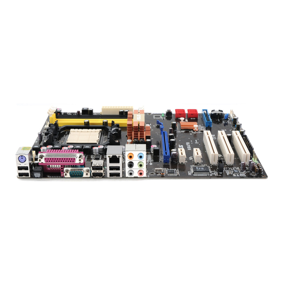
Page 10: Layout Diagram & Jumper Setting
USB Connector Conn. (UL1) (IDE1) AM2 CPU Socket Audio Connector (CN2) 4-pin PWR Connector PCI Express2.0 x16 AMD 770 Chipset by 16-lane Power on Button RealTek RTL 8111CVC Reset Button Gigabit LAN PCI Express2.0 x1 G.P.I. LED AMD SB700 chipset Clear CMOS(JBAT) PCI Express2.0 x16... - Page 11 ATA 133 IDE (UL1) AM2 CPU Socket Conn. (IDE1) Audio Connector (CN2) 4-pin PWR Connector Optional AMD 780G(V) Chipset GPU Memory PCI Express2.0 x16 Power on Button by 16-lane Reset Button RTL 8111CVC Gigabit LAN GPI LED AMD SB700 chipset Clear CMOS (JBAT) PCI Express2.0 x1...
- Page 12 Jumpers Jumper Name Description Page Keyboard/USB Power On Enabled/Disabled 3-pin Block JBAT CMOS RAM Clear 3-pin Block Connectors Connector Name Description Page ATXPWR1 ATX Power Connector 24-pin Block P.14 ATX12V1 ATX 12V Power Connector 8-pin Block P.14 PS/2 Mouse & PS/2 Keyboard Connector 6-pin Female P.15 USB from CN1, UL1...
-
Page 13: Chapter 2 Hardware Installation
Chapter 2 Hardware Installation Turn off your power when adding or removing expansion cards or other WARNING! system components. Failure to do so may cause severe damage to both your motherboard and expansion cards. Hardware installation Steps Before using your computer, you had better complete the following steps: 1. -
Page 14: Install Cpu
2. Forget password 3. After over clocking system boot fail JBAT JBAT 1-2 Closed Normal 2-3 Closed Clear CMOS CMOS RAM Clear Setting Install CPU 2-3-1 Glossary Chipset (or core logic) - two or more integrated circuits which control the interfaces between the system processor, RAM, I/O devises, and adapter cards. -
Page 15: About Amd Athlon64 Socket Am2
2-3-2 About AMD Athlon64 Socket AM2 This motherboard provides a surface mount, Zero Insertion Force (ZIF) socket, referred to as the mPGA940 socket supports AMD Athlon64 processor in the package utilizes Flip-Chip Pin Grid Array package technology. The CPU that comes with the motherboard should have a cooling fan attached to prevent overheating. -
Page 16: Install Memory
Install Memory This motherboard provides two 240-pin DDR II DUAL INLINE MEMORY MODULES (DIMM) socket for DDR II memory SDRAM expandable to maximum memory volume of 4 GB and two 240-pin DDR III SDRAM DUAL INLINE MEMORY MODULES (DIMM) socket for DDR III memory SDRAM expandable to maximum memory volume of 4 GB. Valid Memory Configurations for DDR II Bank 240-Pin DIMM... -
Page 17: Expansion Cards
When you install DIMM module fully into the DIMM socket the eject tab should be locked NOTICE! into the DIMM module very firmly and fit into its indention on both sides. Expansion Cards 2-5-1 Procedure For Expansion Card Installation 1. Read the documentation for your expansion card and make any necessary hardware or software setting for your expansion card such as jumpers. -
Page 18: Pci-Express2.0 Slot
2-5-3 PCI Express 2.0 Slot This motherboard series offers one PCI-Express2.0 x16 By 16-lane graphics slot,one PCI-Express2.0 x16 By 4-lane graphics slots and one PCI-Express2.0 x1 graphics slot for astonishing performance with brilliant and intense 3D graphics The motherboard also carries two 32-bit PCI slots guarantee the rich connectivity for the I/O peripheral devices. -
Page 19: Connectors, Headers
2-6 Connectors, Headers 2-6-1 Connectors Power Connector (24-pin block) : ATXPWR1 ATX Power Supply connector: This is a new defined 24-pins connector that usually comes with ATX case. The ATX Power Supply allows using soft power on momentary switch that connect from the front panel switch to 2-pins Power On jumper pole on the motherboard. - Page 20 (3) PS/2 Mouse & PS/2 Keyboard Connector: KB The connectors are for PS/2 keyboard and PS/2 Mouse. (4) USB Port connector: USB from CN1, UL1 The connectors are 4-pin connector that connects USB devices to the system board. (5) LAN Port connector: RJ-45 LAN from UL1 This connector is standard RJ45 connector for Network which supports 10M/100Mb/1000Mbps data transfer rate Large 4-Pin Power Connector: J2 Power Connector...
- Page 21 (8) Floppy drive Connector (34-pin block): FDD1 This connector supports the provided floppy drive ribbon cable. After connecting the single plug end to motherboard, connect the two plugs at other end to the floppy drives. Pin 1 Floppy Drive Connector (9) Primary IDE Connector (40-pin block): IDE1 This connector supports the provided IDE hard disk ribbon cable.
-
Page 22: Headers
SATA2 SATA1 SATA4 SATA3 SATA6 SATA5 Serial-ATA Port Connectors (11) D-Sub 15-pin connector:VGA VGA connector is the 15-pin D-subminiature female connector; it is for the display devices, such as the CRT monitor, LCD monitor and so on. (12) Digital Visual Interface: DVI This interface standard designed to maximize the visual quality of digital display devices such as flat panel LCD computer displays and digital projectors. - Page 23 (2) USB Port Headers (9-pin): USB1/USB2 These headers are used for connecting the additional USB port plug. By attaching an option USB cable, your can be provided with two additional USB plugs affixed to the back panel. USB1 USB2 Pin 1 Pin 1 USB Port Headers (3) Speaker connector: SPEAK1...
- Page 24 (8) FAN Power Headers: SYSFAN1, SYSFAN2, CPUFAN (4-pin) These connectors support cooling fans of 350mA (4.2 Watts) or less, depending on the fan manufacturer, the wire and plug may be different. The red wire should be positive, while the black should be ground. Connect the fan’s plug to the board taking into consideration the polarity of connector.
- Page 25 (11) Serial Port Header : COM1 COM1 is a 9-pin serial port header. Pin1 Serial COM Port 9-pin Block (12) HDMI_SPDIF Out header: SPDIF Out The SPDIF output is capable of providing digital audio to external speakers or compressed AC3 data to an external Dolby digital decoder. Use this feature only when your stereo system has digital input function.
-
Page 26: Starting Up Your Computer
Starting Up Your Computer 1. After all connection are made, close your computer case cover. 2. Be sure all the switch are off, and check that the power supply input voltage is set to proper position, usually in-put voltage is 220V∼240V or 110V∼120V depending on your country’s voltage used. -
Page 27: Chapter 3 Introducing Bios
Chapter 3 Introducing BIOS The BIOS is a program located on a Flash Memory on the motherboard. This program is a bridge between motherboard and operating system. When you start the computer, the BIOS program will gain control. The BIOS first operates an auto-diagnostic test called POST (power on self test) for all the necessary hardware, it detects the entire hardware device and configures the parameters of the hardware synchronization. -
Page 28: The Main Menu
The Main Menu Once you enter AMI BIOS Setup Utility, the Main Menu (Figure 3-1) will appear on the screen. The Main Menu allows you to select from 12 setup functions and 2 exit choices. Use arrow keys to select among the items and press <Enter> to accept or enter the sub-menu. XBLUE- 77A3 CMOS Setup Utility-Copyright(C)1985-2005 American Megatrends. - Page 29 Integrated Peripherals Use this menu to specify your settings for integrated peripherals. Power Management Features Use this menu to specify your settings for power management. Miscellaneous Control Use this menu to specify your settings for Miscellaneous Control. PC Health Status/Hardware Health Configure This entry shows your PC health status.
-
Page 30: Standard Bios Features
Standard BIOS Features The items in Standard CMOS Setup Menu are divided into several categories. Each category includes no, one or more than one setup items. Use the arrow keys to highlight the item and then use the <+> or <-> and numerical keyboard keys to select the value you want in each item. -
Page 31: Advanced Bios Features
System Date The date format is <day><month><date><year>. Day of the week, from Sun to Sat, determined by BIOS. Read-only. The month from Jan. through Dec. Month The date from 1 to 31 can be keyed by numeric function keys. Date The year depends on the year of the BIOS. - Page 32 XBLUE- 78GA3/XBLUE- 78VA3 CMOS Setup Utility-Copyright(C)1985-2005 American Megatrends. Inc. Advanced BIOS Features Help Item Advanced Settings WARNING: Setting wrong values in below sections May cause system to malfunction Configure CPU CPU Configuration Press Enter Hard Disk Drivers Press Enter Removable Drivers Press Enter Quick Boot Enabled...
-
Page 33: Cpu Configuration
AGESA Version: 3.3.3.0 Physical Count:1 This option should remain Logical Count:2 disabled for the normal operation. The driver AMD Athlon(tm)64x2 Dual Core Processor 4200+ developer may enable it for Revision :G2 testing purposr Cache L1 : 256 KB Cache L2 :1024KB... -
Page 34: Advanced Chipset Features
Advanced Chipset Features The Advanced Chipset Features Setup option is used to change the values of the chipset registers. These registers control most of the system options in the computer. XBLUE- 77A3 CMOS Setup Utility-Copyright(C)1985-2005 American Megatrends. Inc. Advanced Chipset Features Memory Configuration Press Enter Help Item... - Page 35 XBLUE- 78GA3/XBLUE- 78VA3 CMOS Setup Utility-Copyright(C)1985-2005 American Megatrends. Inc. Memory Configuration Help Item DRAM Timing Mode Auto Memory CLK: : 266MHz CAS Latency (Tcl): :4.0 Options RAS/CAS Delay(Trcd): :4 CLK AUTO ROW Precharde Time(Trp) :4CLK DCT0 Min Active RAS(Tras): :12 CLK RAS/RAS Delay (Trrd) :2 CLK Row Cycle(Trc)
-
Page 36: Internal Graphics Configuration
3-6-2 Internal Graphics Configurations XBLUE- 78GA3/XBLUE- 78VGA CMOS Setup Utility-Copyright(C)1985-2005 American Megatrends. Inc. Internal Graphics Configurations Internal Graphics Mode Help Item UMA Frame Buffer Size Auto Options Below 4G GFX Engine Clock Override Enabled Alove 4G Surround View Disabled FB Location Above 4G ↑↓→←... -
Page 37: Integrated Peripherals
Port #02 Features ~ Port #03 Features Press Enter and set values in the sub-items as Ge2 High Speed Mode, Link ASPM, Link width , Slot Power Limit,w and Comliance Mode(780G/780V series motherboard)etc.. Port #04 Features~ Port #10 Features Press Enter and set values in the sub-items as Ge2 High Speed Mode, Link ASPM and Comliance Mode (780G/780V series motherboard)etc.. -
Page 38: Onboard Device Control
XBLUE- 78GA3/XBLUE-78VA3 CMOS Setup Utility-Copyright(C)1985-2005 American Megatrends. Inc. Onboard SATA Device Onchip SATA Channel Enabled Help Item Onchip SATA Type Native IDE Option ROM Combined Mode Enabled Select the time out value for SATA IDECombined Mode Enabled detecting ATA/ATAPI device(s) PATA Channel Config SATA as Primary Onboard PCI IDE Controller... -
Page 39: Super Io Configuration
Onboard PCI E Lan Device Use this item to enable or disable Onboard PCI E Lan HD Audio Azalia Device This item allows you to decide to enable/disable the chipset family to support HD Audio.The optional settings ar: Auto; Enabled and Disabled. USB Configuration Press Enter to set values for sub-items as: Legacy USB Support, USB 2.0 Controller Mode BIOS EHCI Hand-OFF. -
Page 40: Power Management Setup
The optional settings are: IrDA(1.6 ns) and IrDA (3/16 bit). IrDA Duplex Mode/Serial Port 2 Mode This item allows BIOS to select full or half duplex for serial port 2(IR Mode).The optional settings are: Full Duplex; Half Duplex. IrTX Pin Select The optional settings are: Normal and Inverse. -
Page 41: Miscellaneous Control
Advanced ACPI Configuration Use this section to configure additional ACPI options. Power Management/APM Use this item to enable or disable AMI based power management and APM support. Suspend Time Out If it is set Enabled and no activity during this time period, the BIOS will place the system into suspend low power state. -
Page 42: Hardware Health Configure/Pc Health Status
Plug &Play O/S The optional settings are: No; Yes No: Let the BIOS configure all the devices in the system. Yes: Let the operating system configure Plug and Play devices, not required for boot if your system has a Plug and Play system. Allocate IRQ for PCI VGA The optional settings are: No;... -
Page 43: Cpu Thermal Throttling Options
XBLUE- 78GA3/XBLUE-78VA3 CMOS Setup Utility-Copyright(C)1985-2005 American Megatrends. Inc. PC Health Status Help Item PC Health Status Smart FAN Configuration Press Enter H/W Health Function Enabled 50 ° C/122 ° F CPU Temperature: 60 ° C/140 ° F System Temperature: CPUFAN Speed: 2923RPM SYSFAN1 Speed: SYSFAN Speed:... -
Page 44: Power User Overclock Setting
XBLUE- 77A3 CMOS Setup Utility-Copyright(C)1985-2005 American Megatrends. Inc. Power User Overclock Setting Help Item AMD Overclocking Configuration CPU/HT Reference Clock(MHz) Enabled: only AMD over Disabled: Only BIO Ca PCI E Reference Clock (MHz) SB Reference Clock(MHz) Processor Frequency Multiplier Auto... -
Page 45: Bios Security Feature/Password Settings
CPU/HT Reference Clock Use this item to set CPU/HT Reference Clock. The optional setting range is:190~400 MHz. PCI E Reference Clock The optional setting range is:90~250 MHz. SB Reference Clock The optional setting range is:90~150 MHz. Spread Spectrum The optional settings are: Disabled; SRC CLK; CPUHT CLK and All CLK. Processor Voltage The optional settings are: Auto;... -
Page 46: Load Optimal/Failsafe/Standard Defaults
setup menus. When you select this function, the following message will appear at the center of the screen to assist you in creating a password. ENTER PASSWORD: Type the password, up to eight characters in length, and press <Enter>. The password typed now will clear any previously entered password from CMOS memory. -
Page 47: Save Chnges And Exit/Discard And Exit
Load Standard Defaults When you press <Enter> on this item, you get a confirmation dialog box with a message similar to: Load Standard Defaults? 【OK】 【Cancel 】 Pressing <OK> loads the standard default values that are factory settings for stable performance system operations. -
Page 48: Chapter 4 Driver & Free Program Installation
Chapter 4 DRIVER & FREE PROGRAM INSTALLATION Check your package and there is A MAGIC INSTALL CD included. This CD consists of all DRIVERS you need and some free application programs and utility programs. In addition, this CD also include an auto detect software which can tell you which hardware is installed, and which DRIVERS needed so that your system can function properly. -
Page 49: Ati Install Ati Driver Pack
4-1 ATI Install ATI Driver Pack 1. Click ATI appears on the MAGIC INSTALL 2. Click NEXT when ATI software driver pack MENU. appears. 3. Click “Yes” to accept the license agreement 4. Choose whether you would like to restart and and start installation. -
Page 50: Sound Install Al662 Hd Codec Audio Driver
SOUND Install ALC662 HD Audio Driver 1. Click SOUND when MAGIC INSTALL 2. Click NEXT When Realtek High Definition MENU appears Audio driver windows appear 3. Click FINISH and restart your computer 4. Manual Sound Effect Setting 5. Devices and mixer setting 6. -
Page 51: Lan Install Realtek Lan Controller Driver
or later before you the HD Audio CODEC driver. Install RealTek LAN Controller Driver 4-3 LAN 1. Click LAN when Magic Install Menu appears. 2. Click Next to install RealTek LAN Driver. 3. Click Install to begin the installation. 4.After driver installation completed, Click Finish. 4-4 WIFI_N Install RT2770 Wireless Network 1. -
Page 52: Wifi_Bg Install Rtl8187 Wireless Network
3. Select the setup type, theclick Next. 4. Select the configuration tool and then click Next. 5. Click install to begin installation. 6. Click Finish to complete installation. 4-5 WIFI_BG Install RTL8187 Wireless Network 1. Click WIFI_BG on Magic Install menu.. 2.Choose setup language, then click Next. -
Page 53: Raid Install Sata Raid Driver And Utility
5. Decide if you wish to restart the computer then click Finish to complete the installation. 4-6 RAID Install SATA RAID Driver and Utility 1 Click RAIDDisk when MAGIC INSTALL 2. Copy the files to floppy disk and restart the MENU appears computer with floppy disk as the first booting disk and then follow the steps shown on the... -
Page 54: Pc-Health Install Myguard Hardware Monitor Utility
PC-HEALTH Install MyGuard Hardware Monitor Utility 1. Click PC-HEALTH when MAGIC INSTALL 2. Click Next on Install shield wizard Window MENU appears appears。 3. Click Install to begin the installation. 4. Click Finish to complete the installation. 4-9 How to Update BIOS STEP 1. -
Page 55: Amd Platform Raid Function Installation
4-10 AMD Platform RAID Function Installation Please set these choice in the BIOS as RAID:BIOS setup \Integrated Peripherals \Onboard SATA Device \ Onchip SATA Type. When the below figures appeared, please press [Ctrl-F] into figure 2 [figure1] Function: press[1] key, showing the RAID; press [2] key,building RAID; press [3] key, delete the RAID;... - Page 56 1.RAID 1 2. RAID 0 3. RAID 10 4. JBOD [figure4] Choose LD 1 then press Enter. Take Raid0 for example, use [↑] [↓] to shift the cursor, press space key to change the choice, press [Ctrl-Y] to keep. Set Assignment mode as [Y], press [Ctrl-Y] to keep , then figure 5 appeared, erase the MBR. choose [Ctrl-Y],figure 6 appeared.
- Page 57 1: Insert the diskette which is being formatted in floppy drive on a system which can start OS. 2: After booting OS insert the bundle CD in your CD-ROM 3: Copy all the files from\AMD\RAIDDisk to floppy diskette Once you have the SATA driver diskette ready, you may start to install Windows XP,Windows 2000 or vista on your System.
-
Page 58: Pro Magic Plus Function Insruction
Windows 2000 for the proper installation. 4-11 Pro Magic Plus Function Introduction What’s Pro Magic Plus? Tired with reinstall OS each time when it doesn’t work? Does your computer often crash down or unable to work after installed new software? Have you had great loses and troubles because of computer problems? Still using time-consuming backup software that occupies lots of HD space? Pro Magic Plus- an instant system recovery software tailored to solve these problems for you. -
Page 59: G.p.i.function Installation Step
The Default setting in BIOS has already enabled this function. If you wish to change the settings, please enter BIOS and take the following steps: Advanced BIOS Features→CPU Feature→AMD Cool&Quiet Control: Select: AUTO/Disable(This function control the POWER SAVING MODE: Auto/Disabled) CMOS Setup Utility-Copyright(C)1985-2005 American Megatrends. - Page 60 AGESA Version: 3.3.3.0 Physical Count:1 This option should remain Logical Count:2 disabled for the normal operation. The driver AMD Athlon(tm)64x2 Dual Core Processor 4200+ developer may enable it for Revision :G2 testing purposr Cache L1 : 256 KB Cache L2 :1024KB...
- Page 61 Compatible with OS: Windows XP/ 64 series. Users must install CPU driver program(AMD Processor Driver) and select the "Minimal"item in Power Setting. With OS Windows Vista series, there is no need for to take more steps. If needed, please enter...
-
Page 62: Led Display
4-13 G.P.I. LED Display Light on-CPU workload is light and Light off-CPU workload is heavy and motherboard works in power-saving motherboard work in normal mold. -
Page 63: Appendix
Subject 1: Regarding the Application of 3-Phase or 3+1 Phase Power Supply Mold As a result of the increasing power consumption demand from many AMD CPUs in current market, we suggest not to use a CPU that demands more than 65W power... - Page 64 Both the amount of electric current to MOSFET and the heat produced from the motherboard go up as AMD’s CPU power consumption increases. In this case we recommend users select a CPU fan with air outlet towards MOSFET so that CPU fan can carry away heat produced by MOSFET, for better heat dissipation effects.
Need help?
Do you have a question about the 770 and is the answer not in the manual?
Questions and answers