
Related Manuals for EnerSys alpha CXPS-E3


Summary of Contents for EnerSys alpha CXPS-E3
- Page 1 CXPS-E3 200A - 600A Power System User Guide ID: 9400016-J0 Effective: 04/2021 Read this manual carefully. Learn how to protect your equipment from damage and fully understand its functions.
- Page 2 CXPS-E3 Power System 200A - 600A NOTE Photographs contained in this manual are for illustrative purposes only. These photographs may not match your installation. NOTE Operator is cautioned to review the drawings and illustrations contained in this manual before proceeding. If there are questions regarding the safe operation of this powering system, contact Alpha Technologies or your nearest Alpha representative.
-
Page 3: Table Of Contents
CXPS-E3 User Guide Contents 1. Safety ....................6 1.1 Safety symbols ........................... 6 1.2 General safety ..........................6 1.3 Electrical safety .......................... 7 1.4 Battery safety ..........................7 2. Introduction ..................8 2.1 Scope of the manual ........................8 2.2 Product overview ........................8 2.3 ... - Page 4 User Guide CXPS-E3 6.1 Safety precautions ........................29 6.2 Tools required .......................... 29 6.3 Installation of external batteries ....................29 6.4 Battery maintenance report ...................... 31 6.5 Power system assembly and mounting ................... 32 6.6 Breaker installation ........................34 7. Wiring ....................35 7.1 Installation notes ........................
- Page 5 CXPS-E3 User Guide Figures Figure 1 — CXPS-E3 system ......................8 Figure 2 — 19 inch CXPS-E3 with 2.4kW | 3.0kW rectifiers ............. 9 Figure 3 — 23 inch CXPS-E3 with 2.4kW | 3.0kW rectifiers ............10 Figure 4 — 19 inch CXPS-E3 with 4.0kW | 4.6kW rectifiers ............10 Figure 5 — 23 inch CXPS-E3 with 4.0kW | 4.6kW rectifiers ............11 Figure 6 — 23 inch CXPS-E3 with 3.0kW rectifiers .................11 Figure 7 — Front panel with L-ADIO and Cordex HP controller ............. 16 Figure 8 —...
- Page 6 User Guide CXPS-E3 9400016-J0 Rev E...
-
Page 7: Safety
CXPS-E3 User Guide 1. Safety Save these instructions This manual contains important safety instructions that must be followed during the installation, servicing, and maintenance of the product. Keep it in a safe place. Review the drawings and illustrations contained in this manual before proceeding. -
Page 8: Electrical Safety
User Guide CXPS-E3 1.3 Electrical safety WARNING! Hazardous voltages are present at the input of power systems. The DC output from rectifiers and batteries, though not dangerous in voltage, has a high short-circuit current capacity that may cause severe burns and electrical arcing. Before working with any live battery or power system, follow these precautions: a. -
Page 9: Introduction
CXPS-E3 User Guide 2. Introduction 2.1 Scope of the manual This manual covers the features, options, installation, and startup of Alpha Technologies CXPS-E3 power system. Images contained in this document are for illustrative purposes only and may not exactly match your installation. -
Page 10: System Configurations
User Guide CXPS-E3 2.3 System configurations The following five configurations are currently available for the CXPS-E3 power system. For more ordering information, refer to the CXPS-E3 Ordering Guide on the Alpha website. Table A — CXPS-E3 configuration Rack size Controller Expanded Current Rectifier capacity Load... -
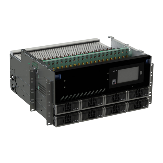
Page 11: Figure 3 - 23 Inch Cxps-E3 With 2.4Kw | 3.0Kw Rectifiers
CXPS-E3 User Guide 2.3.2 CXPS-E3 23 inch systems with 2.4kW | 3.0kW rectifiers • Rated for 400A with two 2.4kW | 3.0kW shelves • 5RU with two 2.4kW | 3.0kW shelves • 26 load breakers with load shunt or 21 load and 5 battery breakers with LVBD • Cordex HP controller •... -
Page 12: Figure 5 - 23 Inch Cxps-E3 With 4.0Kw | 4.6Kw Rectifiers
User Guide CXPS-E3 2.3.4 CXPS-E3 23 inch systems with 4.0kW | 4.6kW rectifiers • Rated for 400A with one 4.0kW | 4.6kW shelf • 7RU with one 4.0kW | 4.6kW shelf • 26 load breakers with load shunt or 21 load and 5 battery breakers with LVBD • Cordex HP controller •... -
Page 13: Specifications
CXPS-E3 User Guide 3. Specifications Table B — 48V–2.4kW | 3.0kW, 4.0kW | 4.6kW 400A CXPS-E3 systems Electrical 48V, 2.4kW | 3.0kW 48V, 4.0kW | 4.6kW System capacity (max.) 400A 400A Operating voltage 208 to 277Vac (nominal) 208 to 277Vac (nominal) Extended (high) 277 to 310Vac 277 to 310Vac... - Page 14 User Guide CXPS-E3 Table C — 48V–3.0kW 600A systems Electrical System Capacity (max) Systems with LVBD Systems without LVBD 625A total 625A total Amperage 550A load 550A battery Operating voltage 208 to 277Vac (nominal) Extended (high) 277 to 310Vac Extended (low) 90 to 187Vac (de-rated O/P power) Input Recommended AC...
-
Page 15: Features
CXPS-E3 User Guide 4. Features 4.1 Seismic racks The CXPS-E3 system can be installed in a variety of Alpha provided, 19" and 23" seismic racks. These racks have been Z4 rated and NEBS L3 certified. The racks vary in their Z4 seismic capabilities from 500lb to 2500lb and in their heights from a 3.5' to 9' (standard 7' racks are available as well). - Page 16 User Guide CXPS-E3 4.2.2 400A 23inch power center Provides up to 26 breakers which can be configured as all load breakers (26 load breakers) or a mix of load and battery breakers (21 load breakers and 5 battery breakers). The all load breaker configuration has a shunt that monitors the total load current supplied by the rectifiers to the load.
-
Page 17: Front Panel With A Cordex Hp Controller
CXPS-E3 User Guide 4.3 Front panel with a Cordex HP controller The front panel includes the Cordex HP controller and a pre-wired L-ADIO module. The Cordex HP family of products provide centralized setup, control and monitoring of power systems. This can range from simple monitoring and threshold alarms for temperature, voltage and current, to advanced battery charging and diagnostic features. -
Page 18: L-Adio
User Guide CXPS-E3 The Cordex HP has the following features: Front touch screen Full color LCD touch screen display, to access controls and menu items by using fingertip touch or a stylus. Home button Provides the ability to go directly back to the home screen from any menu. Front panel reset For emergency use only to restart the Cordex HP if the unit touch screen or home button are not responding. -
Page 19: Figure 9 - L-Adio Io Peripheral
CXPS-E3 User Guide Bus B Voltage Bus A Voltage CAN Ports CAN Ports Bus B Alarm Power Input Bus A Alarm Figure 9 — L-ADIO IO peripheral 4.4.6 Network connection and remote communications The system can be set up, monitored, and tested via an Ethernet 10/100 Base-T serial data connection. The communication protocol supports a web interface. -
Page 20: Kw Rectifier
User Guide CXPS-E3 4.5 2.4kW rectifier 4.5.1 Rectifier features • High performance compact 50A rectifier for 48Vdc telecom applications • High efficiency (96 +%) for reduced OPEX and carbon footprint • High temperature operating range for installation in non-controlled environments • Multiple configurations providing 250A or 12kW in a compact 1RU shelf • High power density (28W/in ) yields more space for revenue generating equipment • Wide AC input operating range for global installation requirements •... -
Page 21: Rectifier Front Panel Leds
CXPS-E3 User Guide 4.9 Rectifier front panel LEDs The front panel LEDs indicate the rectifier status summary and patterned response to Locate Module command. The red LED is on during an active Module Fail alarm if the module is unable to source power due to a fault condition. Refer to the relevant controller manual for fault details. -
Page 22: 400A Lvd Override
User Guide CXPS-E3 4.10 400A LVD override For systems with LVBD an override interface is provided, see Figure 10. This interface board includes three LEDs indicators to provide visual status indication, and two customer connections for remote control and monitoring: Figure 10 —... -
Page 23: Figure 12 - Lvd Override Connections
CXPS-E3 User Guide The LVD override interface is configured for remote control by default for most systems. To change configuration: This operation must be done with AC and DC power disconnected, ideally prior to commissioning the system. 1. Remove the interface from the CXPS-E3 by removing the two screws from the front 2. -
Page 24: 600A Lvd Override
User Guide CXPS-E3 4.11 600A LVD override 4.11.1 Introduction Contactors are mechanical switches, which connect and disconnect high current power sources and electrical load, for example between rectifiers and batteries or loads in a power system. The CXPS-E3 600A takes advantage of the higher efficiency and smaller form factor of a latching contactor, along with heavier bus work, to enable a much higher current rating than the original CXPS-E3 in the same physical volume. - Page 25 CXPS-E3 User Guide attempts to reclose it within 2-3 seconds. In the case where the state remains incorrect the Cordex HP attempts to correct it up to three consecutive times. After those three attempts it generates a user alarm and waits 15 minutes before trying again. This overall cycle of three attempts followed by a 15 minute pause continues until the contactor changes state, is disabled, or serviced.
- Page 26 User Guide CXPS-E3 Power LED simply provides the status that either one of these sources is present. Latching interface background The LVD Control Interface (LCI) translates the L-ADIO control relay state change into a fixed duration high current pulse to the contactor, thus preventing the contactor coil from being continuously powered in case of operator or controller error.
-
Page 27: Integrated Battery Trays
CXPS-E3 User Guide 4.12 Integrated battery trays The CXPS-E3 system is designed to integrate battery trays below the power system. These battery trays can accept standard 12V mono-blocks ranging in height from 6RU-8RU. The battery trays are factory installed and pre-wired for ease of installation. -
Page 28: Figure 14 - Battery Landing Busbar Kit
User Guide CXPS-E3 1.00 TYP 1.00 TYP 1.00 TYP Figure 14 — Battery landing busbar kit 9400016-J0 Rev E... -
Page 29: Inspection
CXPS-E3 User Guide 5. Inspection 5.1 Packing materials Alpha Technologies is committed to providing products and services that meet our customers’ needs and expectations in a sustainable manner, while complying with all relevant regulatory requirements. As such Alpha Technologies strives to follow our quality and environmental objectives from product supply and development through to the packaging for our products. -
Page 30: Installation
User Guide CXPS-E3 6. Installation Only qualified personnel should install and connect the power components within the Alpha power system. For the battery installation, refer primarily to the manufacturer’s manual. Frequent reference is made to drawings located at the end of this manual. 6.1 Safety precautions Refer to the Safety section near the front of this manual. - Page 31 CXPS-E3 User Guide 6.3.1 Installing the batteries Verify that all battery breakers, DC circuit breakers, and fuses on the distribution panels are either in the OFF position or removed. Apply a corrosion-inhibiting agent, such as NO-OX-ID “A”, on all battery terminal connections. 1.
-
Page 32: Battery Maintenance Report
User Guide CXPS-E3 6.4 Battery maintenance report After assembly, number the batteries and take “as received” readings, including specific gravity, cell voltage, and temperature. Designate one cell as the pilot cell. This is usually the cell with either the lowest specific gravity or voltage. -
Page 33: Power System Assembly And Mounting
User Guide CXPS-E3 6.5 Power system assembly and mounting The power system must be mounted in a clean and dry environment. Sufficient free space must be provided at the front and back of the power system. This is to meet the cooling requirements of the rectifiers and to allow easy access to the power system components. -
Page 34: Figure 15 - Rack Mounting Details (Top View), Welded Rack
User Guide CXPS-E3 28.1 24.3 21.0 6.0 TYP 16.0 12.3 5.25 4.03 5.25 TYP Figure 15 — Rack mounting details (top view), welded rack 0.75 THRU .94 X .325 SLOT TRHU 15.00 9.63 13.00 18.14 23.50 25.50 Figure 16 — Rack mounting details (top view), bolted rack 6.5.2 Rack mounted systems Attach the power system to the customer-provided relay rack using mounting screws and star washers to ensure an electrical bond between system chassis and relay rack. -
Page 35: Breaker Installation
CXPS-E3 User Guide 6.5.3 Systems mounted in outdoor enclosures (operated above 40°C) Attach the power system to the customer-provided enclosure using mounting screws and star washers to ensure an electrical bond between system chassis and relay rack. The 19" and 23" CXPS-E3 systems may be either flush or center mounted in the enclosure. -
Page 36: Wiring
User Guide CXPS-E3 7. Wiring This chapter provides cabling details and notes on cable sizing for DC applications with respect to the product. WARNING! Ensure that the power is switched off by switching off rectifiers and removing battery line fuses, turn off battery breakers before attempting work on the wiring. -
Page 37: Grounding
CXPS-E3 User Guide Table F — Cable size equivalents (AWG to Metric) Cable size Circular mils Square millimeters Equivalent metric cable 2 AWG 66370 33.63 0 AWG (or 1/0) 105600 53.48 50 or 70 00 AWG (or 2/0) 133100 67.42 0000 AWG (or 4/0) 211600 107.2... -
Page 38: Figure 18 - Connecting The Frame Ground To The Cxps-E3
User Guide CXPS-E3 7.2.1 Frame ground There are several options for connecting a frame ground to the CXPS-E3 (select just one option): • The options highlighted on either side of the CXPS-E3 distribution. • As highlighted in the 2.4kW or 3.0kW user guide, a back connection on the side of the AC termination box. •... - Page 39 CXPS-E3 User Guide 7.2.2 Reference ground The reference ground should be connected between the building master ground bus (MGB) or floor ground bus (FGB) and the power system power system internal battery return bus (BRB) in ONLY ONE location. If the MGB or FGB is connected to the power system BRB in more than one location then load current will circulate through the reference ground bond, creating and unsafe condition known as “ground loop”.
-
Page 40: Ac Wiring
User Guide CXPS-E3 7.3 AC wiring To ease future access issues, connect the AC circuits to all rectifier shelves at the time of initial installation. NOTE Verify NO rectifiers are installed in the rectifier shelves at this time. 7.3.1 AC feeder protection and sizing To maximize system reliability, each feed should have a dedicated protection feeder breaker located at the AC distribution panel. -
Page 41: Dc Wiring
CXPS-E3 User Guide 7.4.2 AC wiring for 4.0kW | 4.6kW rectifier shelf The 4.0kW | 4.6kW rectifier shelves used within the CXPS-E3 systems are 19- or 23 inches in width. The individual rectifier shelves are wired to the customer provided AC termination panel. The AC input is routed through a 1 inch trade size knockout on the side of the shelf for a direct connection. -
Page 42: Distribution Cabling
User Guide CXPS-E3 7.5 Distribution cabling 7.5.1 Load planning and breaker (fuse) spacing CAUTION! and HOT! For applications when the CXPS-E3 is subjected to ambient temperatures above 55°C it must be installed inside equipment such that unintentional contact with the area of the side panels between the mid-mount bracket and the back of the unit is unlikely. -
Page 43: Alarm And Signal Connection
User Guide CXPS-E3 7.6 Alarm and signal connection The IO capabilities of the CXPS-E3 system allow the user to extend various alarm or control signals to an external site monitor via output relays or monitor various analog and digital signals via analog and digital inputs. For terminal block connections, the recommended wire sizes are 0.14 to 1.50mm²... -
Page 44: Network And Remote Communication
User Guide CXPS-E3 7.6.4 Programming the digital input The digital input channels can be programmed for “active high” or “active low.” Active high indicates “alarm on the presence of a ground signal” and active low indicates “alarm on the removal of a ground signal.” See the controller software manual for detailed instruction on programming. -
Page 45: Signal Wiring
CXPS-E3 User Guide 7.9 Signal wiring 1. Use the Form C relay contacts on the L-ADIO to extend various alarm or control signals to an external site monitor. Figure 27 shows the L-ADIO module layout. Table J lists the factory default settings. 2. -
Page 46: System Startup
User Guide CXPS-E3 8. System startup After completing the system installation and power system wiring, perform the following startup and test procedure to ensure proper operation. 1. Visually inspect the installation thoroughly. 2. Verify: • AC input power is off. • batteries are disconnected. •... - Page 47 CXPS-E3 User Guide 8.9.1 Factory ranges and defaults Table K lists the rectifier settings, ranges, and defaults. Changes are made through the controller interface. Table K — Rectifier factory ranges and defaults Setting Range (minimum to maximum) Default Float (FL) voltage 47.5V –...
-
Page 48: Maintenance
User Guide CXPS-E3 9. Maintenance Although very little maintenance is required with Alpha systems, routine checks and adjustments are recommended to ensure optimum system performance. Qualified service personnel should do the repairs. The following table lists a few maintenance procedures for this system. These procedures should be performed at least once a year. -
Page 49: 400A Lvd Override Operation
User Guide CXPS-E3 9.1 400A LVD override operation CAUTION! Before removing a controller from a live system or performing controller maintenance, an external LVD override is required to avoid a disruption of service. The LVD Control functions are hardwired directly from the assigned relay output to an optional LVD override control located in the CXPS-E3 distribution panel below the breakers. -
Page 50: Acronyms And Definitions
User Guide CXPS-E3 10. Acronyms and definitions Alternating current ANSI American National Standards Institute American Wire Gauge British thermal unit Controller area network Canadian Electrical Code Canadian Standards Association Cordex™ series; CXC for Cordex System Controller Direct current DHCP Dynamic Host Configuration Protocol Electronic Industries Alliance Electromagnetic compatibility Electromagnetic interference... -
Page 51: Warranty Statement And Service Information
CXPS-E3 User Guide 11. Warranty statement and service information 11.1 Technical support In Canada and the USA, call toll free +1.888.462.7487 Customers outside Canada and the USA, call +1.604.436.5547 11.2 Warranty statement For full information details review Alpha's online Warranty statement at www.alpha.ca/support. 11.3 Product warranty Alpha warrants that for a period of two years from the date of shipment its products shall be free from defects under normal authorized use consistent with the product specifications and Alpha’s instructions, the terms of the... -
Page 52: Certification
User Guide CXPS-E3 12. Certification About CSA and NRTL CSA (Canadian Standards Association also known as CSA International) was established in 1919 as an independent testing laboratory in Canada. CSA received its recognition as an NRTL (Nationally Recognized Testing Laboratory) in 1992 from OSHA (Occupational Safety and Health Administration) in the United States of America (Docket No. - Page 62 User Guide CXPS-E3 Notes 9400016-J0 Rev E...
- Page 63 CXPS-E3 User Guide Notes 9400016-J0 Rev E...
- Page 64 Alpha Technologies Ltd. | 7700 Riverfront Gate, Burnaby, BC V5J 5M4 CANADA Toll Free North America: +1.800.667.8743 | Outside North America +1.604.436.5547 | Technical Support +1.888.462.7487 For more information visit our website at: www.alpha.com © 2021 Alpha Technologies Ltd. All Rights Reserved. Trademarks and logos are the property of Alpha Technologies Ltd. and its affiliates www.alpha.com unless otherwise noted.
Need help?
Do you have a question about the alpha CXPS-E3 and is the answer not in the manual?
Questions and answers