Sign In
Upload
Manuals
Brands
EnerSys Manuals
Power Supply
alpha CXPS-E3
EnerSys alpha CXPS-E3 Manuals
Manuals and User Guides for EnerSys alpha CXPS-E3. We have
2
EnerSys alpha CXPS-E3 manuals available for free PDF download: Manual, User Manual
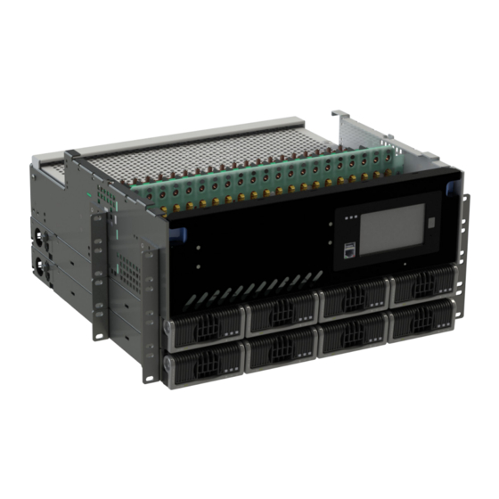
EnerSys alpha CXPS-E3 Manual (76 pages)
Edge Power Systems
Brand:
EnerSys
| Category:
Power Supply
| Size: 16 MB
Table of Contents
Table of Contents
4
1 Safety
7
Safety Symbols
7
General Warning and Cautions
7
Electrical Safety
8
Battery Safety
8
2 Introduction
9
Document Scope
9
Product Overview
9
Figure 1: Cordex® CXPS-E3 400 a Edge Power System (19-Inch)
9
System Configurations
10
Figure 2: Cordex® CXPS-E3 300 a Edge Power System (19-Inch) with One 2.4/3.0 Kw Rectifier Shelf
10
Figure 3: Cordex® CXPS-E3 300 a Edge Power System (23-Inch) with One 2.4/3.0 Kw Rectifier Shelf
11
Figure 4: Cordex® CXPS-E3 400 a Edge Power System (19-Inch) with Two 2.4/3.0 Kw Shelves
11
Figure 5: Cordex® CXPS-E3 400 a Edge Power System (23-Inch) with Two 2.4/3.0 Kw Shelves
11
Figure 6: Cordex® CXPS-E3 400 a Edge Power System (19-Inch) with One 4.0/4.6 Kw Shelf
12
Figure 7: Cordex® CXPS-E3 400 a Edge Power System (23-Inch) with One 4.0/4.6 Kw Shelf
12
Figure 8: Cordex® CXPS-E3 600 a Edge Power System (23-Inch) with Two 2.4/3.0 Kw Shelves
13
Figure 9: Cordex® CXPS-E3 900 a Edge Power System (23-Inch) with Three 2.4/3.0 Kw Shelves
13
3 Specifications
14
Cordex® CXPS-E3 300 a Edge Power Systems
14
Cordex® CXPS-E3 400 a Edge Power Systems
15
Cordex® CXPS-E3 600 a Edge Power Systems
17
Cordex® CXPS-E3 900 a Edge Power Systems
18
4 Features
19
Seismic Racks
19
Distribution Panels
19
Control and Monitoring Methods
20
Front Panel with Controller and ADIO Peripheral
22
Figure 10: Front Panel with Cordex® CXC HP Controller and Cordex® CXC HP L -ADIO Peripheral
22
Figure 11: Cordex® CXC HP Controller
22
Figure 12: Cordex® CXC HP L -ADIO Smart Peripheral
24
Cordex® HP 2.4 Kw Rectifiers
25
Cordex® HP 3.0 Kw Rectifiers
25
Cordex® HP 4.0 Kw Rectifiers
25
Cordex® HP 4.6 Kw Rectifiers
25
Rectifier Front Panel Leds
26
300 A and 400 a LVD Override
27
Figure 13: LVD Override
27
Figure 14: LVD Override Interface
27
Figure 15: LVD Override Connections
28
600 A LVD Override
29
Integrated Battery Trays
32
Battery Landing Busbar Kit
32
Figure 16: Integrated Battery Tray
32
Figure 17: Battery Landing Busbar Kit
33
5 Inspection
34
Packing Materials
34
Returns for Service
34
Check for Damage
34
General Receipt of Shipment
34
Miscellaneous Small Parts
34
6 Installation
35
Safety Precautions
35
Tools Required
35
Installation of External Batteries
35
Battery Maintenance Report
37
Power System Assembly and Mounting
38
Figure 18: Rack Mounting Details (Top View), Welded Rack
39
Figure 19: Rack Mounting Details (Top View), Bolted Rack
39
Breaker Installation
40
Figure 20: Breaker Installation
40
7 Wiring
41
Installation Notes
41
Grounding
42
Figure 21: Connecting the Frame Ground to the Power System
43
Figure 22: Connecting the Frame Ground to Overhead Trays
43
AC Wiring
45
Figure 23: AC Input and Ground for 23-Inch Shelf
46
DC Wiring
47
Figure 24: Shelf AC Connection (Three-Phase, Three-Wire Shown with Back Cover Removed)
47
Distribution Cabling
48
Alarm and Signal Connection
49
Figure 25: Alarm (Relay) Connections
49
Figure 26: Digital Input Connection Method
50
Network and Remote Communication
51
Connecting Battery Temperature Sensor
51
Figure 27: Battery Temperature Sensor
51
Figure 28: Battery Temperature Sensor, Battery Bay
51
Signal Wiring
52
Figure 29: Relay Connections, Not Energized State
52
Figure 30: Alarm Relay Pinouts
52
8 System Startup
53
9 Maintenance
55
Controller Lithium Battery Replacement
56
Figure 31: Controller Battery Replacement
56
300 A and 400 a LVD Override Operation
57
600 A LVD Override Operation
57
10 Acronyms and Definitions
58
Advertisement
EnerSys alpha CXPS-E3 User Manual (64 pages)
Power System
Brand:
EnerSys
| Category:
Power Supply
| Size: 10 MB
Table of Contents
Table of Contents
3
1 Safety
7
Safety Symbols
7
General Safety
7
Electrical Safety
8
Battery Safety
8
2 Introduction
9
Scope of the Manual
9
Product Overview
9
Figure 1 - CXPS-E3 System
9
System Configurations
10
Figure 2 - 19 Inch CXPS-E3 with 2.4Kw | 3.0Kw Rectifiers
10
Figure 3 - 23 Inch CXPS-E3 with 2.4Kw | 3.0Kw Rectifiers
11
Figure 4 - 19 Inch CXPS-E3 with 4.0Kw | 4.6Kw Rectifiers
11
Figure 5 - 23 Inch CXPS-E3 with 4.0Kw | 4.6Kw Rectifiers
12
Figure 6 - 23 Inch CXPS-E3 with 3.0Kw Rectifiers
12
3 Specifications
13
4 Features
15
Seismic Racks
15
Distribution Centers
15
Front Panel with a Cordex HP Controller
17
Figure 7 - Front Panel with L-ADIO and Cordex HP Controller
17
Figure 8 - Cordex HP Controller
17
L-Adio
18
Figure 9 - L-ADIO IO Peripheral
19
Kw Rectifier
20
Rectifier Front Panel Leds
21
400A LVD Override
22
Figure 10 - LVD Override
22
Figure 11 - LVD Override Interface
22
Figure 12 - LVD Override Connections
23
600A LVD Override
24
Integrated Battery Trays
27
Battery Landing Busbar Kit
27
Figure 13 - Integrated Battery Tray
27
Figure 14 - Battery Landing Busbar Kit
28
5 Inspection
29
Packing Materials
29
Check for Damage
29
General Receipt of Shipment
29
6 Installation
30
Safety Precautions
30
Tools Required
30
Installation of External Batteries
30
Battery Maintenance Report
32
Power System Assembly and Mounting
33
Figure 15 - Rack Mounting Details (Top View), Welded Rack
34
Figure 16 - Rack Mounting Details (Top View), Bolted Rack
34
Breaker Installation
35
Figure 17 - Breaker Installation
35
7 Wiring
36
Installation Notes
36
Grounding
37
Figure 18 - Connecting the Frame Ground to the CXPS-E3
38
Figure 19 - Connecting the Frame Ground to Overhead Trays
38
AC Wiring
40
Figure 20 - AC Input and Ground for 23Inch Shelf
40
DC Wiring
41
Figure 21 - Shelf AC Connection (Three-Phase, Three-Wire Shown with Back Cover Removed)
41
Distribution Cabling
42
Alarm and Signal Connection
43
Figure 22 - Alarm (Relay) Connections
43
Figure 23 - Digital Input Connection Method
43
Network and Remote Communication
44
Connecting Battery Temperature Probes
44
Figure 24 - Battery Temperature Probes
44
Figure 25 - Battery Temperature Probes, Battery Bay
44
Signal Wiring
45
Figure 26 - Relay Connections, Not Energized State
45
Figure 27 - Alarm Relay Pinouts
45
8 System Startup
46
9 Maintenance
48
400A LVD Override Operation
49
10 Acronyms and Definitions
50
11 Warranty Statement and Service Information
51
Technical Support
51
Warranty Statement
51
Product Warranty
51
Battery Warranty
51
Warranty Claims
51
Service Information
51
12 Certification
52
Advertisement
Related Products
EnerSys alpha Cordex CXPS-E105
EnerSys alpha Cordex CXRF 48-3.6kW
EnerSys alpha Cordex HP CXRF 48-12kW
EnerSys alpha Cordex HP CXRF 48-4.0kW
EnerSys alpha Cordex HP CXRF 48-4.6kW
EnerSys Alpha FMPS FTTP
EnerSys Alpha Broadband UPS
EnerSys alpha LPS36
EnerSys alpha APX3-G Series
EnerSys alpha APX3-608G
EnerSys Categories
Camera Accessories
Battery Pack
Battery Charger
Power Supply
Industrial Equipment
More EnerSys Manuals
Login
Sign In
OR
Sign in with Facebook
Sign in with Google
Upload manual
Upload from disk
Upload from URL