
Related Manuals for EnerSys Alpha FMPS FTTP


Summary of Contents for EnerSys Alpha FMPS FTTP
- Page 1 FMPS FTTP Multipurpose Power Supply Installation & Operation Manual: 010-592-B2 Effective: 09/2020...
- Page 3 SAFETY NOTES SAVE THESE INSTRUCTIONS Review the drawings and illustrations contained in this manual before proceeding. If there are any questions regarding the safe installation or operation of the system, contact Alpha Technologies or your nearest Alpha representative. Save this document for future reference. To reduce the risk of injury or death, and to ensure the continued safe operation of this product, the following notations/symbols have been placed throughout this manual.
- Page 4 General Safety Precautions To avoid injury: • Read and follow all installation, equipment grounding, usage, and service instructions included in this manual. • Disconnect power before servicing. • This enclosure and its associated hardware must be serviced only by authorized personnel. •...
- Page 5 Battery Safety Notes WARNING! Lead-acid batteries contain dangerous voltages, currents and corrosive material. Battery installation, maintenance, service and replacement must be performed only by authorized personnel. Chemical Hazards Any gelled or liquid emissions from a valve-regulated lead-acid (VRLA) battery contain dilute sulfuric acid, which is harmful to the skin and eyes.
- Page 6 Battery Maintenance Guidelines The battery maintenance instructions listed below are for reference only. Battery manufacturer’s instructions for transportation, installation, storage or maintenance take precedence over these instructions. • To prevent damage, inspect batteries every three months for: Signs of battery cracking, leaking or swelling. The battery should be replaced immediately by authorized personnel using a battery of the identical type and rating.
- Page 7 Grounding Connection Notes In order to provide a ready, reliable source of backup power it is necessary to establish a grounding system that not only provides for the safety of the service personnel responsible for its operation and maintenance, but also facilitates the proper operation and protection of the equipment within the network.
-
Page 9: Table Of Contents
ABLE OF ONTENTS ECTION ................................1 NTRODUCTION Scope of the Manual ............................. 1 Product Overview ............................1 ............................... 3 HEORY OF PERATION Operating States ............................3 Exception States ............................4 Status Signals ............................... 4 ..........................5 RANSPORTATION AND TORAGE ................................6 NSTALLATION Enclosure Preparation ........................... - Page 10 A ................................21 PPENDIX Installing the FMPS Power Module as a Stand-alone Unit ................. 21 10 A B ................................22 PPENDIX 10.1 Installing the FMPS Power Module in a 19” or 23” Rack Mount Chassis ........... 22 11 W ................................23 ARRANTY 11.1 Technical Support ............................
-
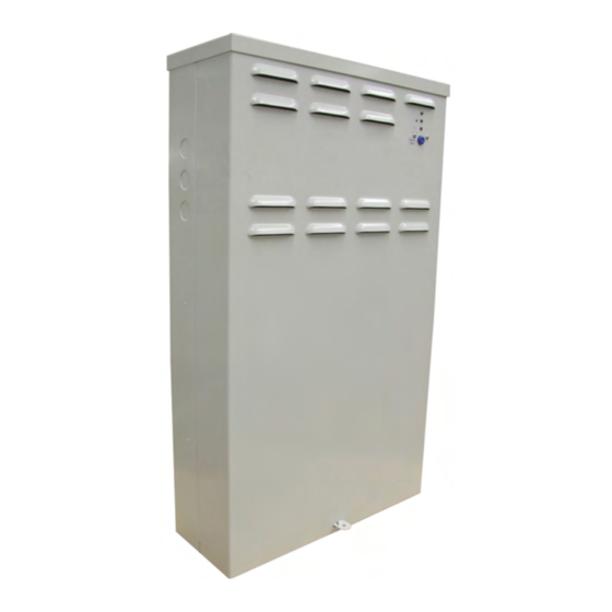
Page 11: Introduction
Introduction Scope of the Manual This instruction manual explains the features, installation, startup and maintenance of the FMPS FTTP Multipurpose Power Supply. NOTE: Images contained in this document are for illustrative purposes only and may not exactly match your installation. Product Overview The FMPS, model number FMPS-150W, is an intelligent microprocessor-controlled 48Vdc UPS system. - Page 12 #10 ONT ground reference stud (2 PL) LED indicators Battery string (A, B) status LEDs Silence alarm button Audible alarm ON/OFF Safety ground stud and AC input block Output (1, 2) and alarm connections Battery string A connections (4 PL) Battery string B connections (4 PL) Factory installed heater option 8’...
-
Page 13: Theory Of Operation
Theory of Operation Operating States The FMPS has two operating states, Normal Operation and Battery Backup. 2.1.1 Normal Operation The FMPS supplies power to the ONT, while being powered by the AC mains outlet. It may also be charging the batteries or performing a battery test. -
Page 14: Exception States
Exception States While in Normal Operation or Battery Backup, there are three exception states that may occur. 2.2.1 Replace Battery The FMPS enters the Replace Battery state when the charge control circuit determines the battery is not holding a charge, or is incapable of being charged. The Replace Battery alarm initiates when the battery capacity is less than 70% of the battery capacity stated by the battery manufacturer. -
Page 15: Transportation And Storage
Transportation and Storage 3.1.1 Packaging The enclosure and components are shipped on individual pallets and shrink wrapped. The pallet is approximately 0.15m H x 1.22m W x 1.52m D (6” H x 48” W x 60” D) and the overall height including pallet and enclosure is approximately 0.46m (18”). -
Page 16: Installation
Installation The information in this section is intended as a guideline only; there may be site-specific requirements and other factors that will require individual attention, such as jurisdictional codes and construction covenants. The FMPS can be installed by one technician during a single visit to the customer premises. The FMPS can be mounted on an internal or external customer premises wall, or it can be recessed into a newly framed wall during new construction. -
Page 17: Removing The Fmps Cover
Removing the FMPS Cover 1. Remove the Phillips screw securing the cover. 2. Grasp the cover by the sides and lift up slightly (see Figure 3). 3. Swing the bottom of the cover out and away from the unit (see Figure 4). Figure 3–Lifting the FMPS cover Figure 4–Sliding the FMPS cover out Wall-mounting the FMPS... -
Page 18: Recessed/Stud-Mounting The Fmps
Recessed/Stud-mounting the FMPS 1. Select a suitable location for mounting the FMPS. 2. After removing the cover, unscrew the battery retaining brackets. 3. Drill four 3/8” holes in the side of the enclosure using the pressed dimples in the side of the enclosure as a guide. -
Page 19: Safety Ground
Safety Ground The safety ground is a two-part system. The first part is a return path for stray current back to the input breaker, and the second is a return path from the enclosure to a second ground rod. Typically, the safety, or utility ground, provides a return path to the input breaker or fuse panel by means of a connection to an appropriate driven ground rod at the base of the power pole. -
Page 20: Ac Wiring, Permanent Connection
4.10 AC Wiring, Permanent Connection 1. Run the AC wiring through the 1/2" EMT along the same path as the original AC line cord. 2. Connect the AC wiring as follows: • Black wire = Line • White wire = Neutral 3. -
Page 21: Dc Output And Alarm Wiring
4.11 DC Output And Alarm Wiring Recommended wire size: • DC output: 2 x #16 AWG • Alarm wiring: 5 x #24 AWG • Ground: #16 AWG 1. If wall-mounting the FMPS, select a knockout to the right of the DC output block and remove it using a hammer and punch. -
Page 22: Battery Installation
Battery Installation WARNING! Follow battery manufacturer’s safety recommendations when working around battery systems and review the safety instructions provided in this manual. Batteries must be rated at the same capacity, and must be equal in age and quality. Preparation/Mounting The Enclosure must be mounted (Section 4) before installation of the bottom tray of batteries may be completed. Batteries should be located in a temperature-controlled environment. - Page 23 5. Slide the battery blocks onto the battery trays starting at the bottom (four per tray). NOTE: When only one string of batteries is installed, thermal performance will be better on the bottom tray. 6. Secure the battery bracket thumbscrews. See Figure 11. 7.
- Page 24 Company: ________________________________________________ Date: ____________________ Address: ____________________________________________________________________________ Battery location and/or number: __________________________________________________________ No. of cells: _______________ Type: __________________________ Date new: ________________ Date installed: _____________ Float voltage: ____________________ Ambient temp.: ____________ Battery Readings Battery # Serial # Voltage Specific Ohms Mhos Observations Gravity Remarks and recommendations: _________________________________________________________ __________________________________________________________________________________...
-
Page 25: Operation
Operation Start-up 1. Apply AC power by a) plugging the unit into AC power outlet, b) turning on the AC feeder breaker, or c) connecting the IEC (option) to specified source. 2. Verify no alarms are active and the green power indicator is lit. 3. -
Page 26: Audible Alarm
Audible Alarm The Audible Alarm switch is located inside the unit below the status LEDs. Its default position is OFF. If enabled, the audible alarm gives a low battery warning of four short beeps once an hour when the battery string voltage reaches 46.8V. -
Page 27: Battery Self-Test
6.10 Battery Self-test The FMPS performs an automatic Battery Self-test on a cycle of one string every 22.5 days. The battery self-test operates as follows: 1. The microprocessor verifies that AC power is on. 2. If AC is present the microprocessor initiates the self-test. 3. -
Page 28: Test And Commissioning (Overview)
Test and Commissioning (Overview) System All Alpha power system components undergo thorough factory testing. All levels/alarms are set to predetermined values as detailed in their individual component manuals except where custom levels are specified. Good installation practice is to check the operation of all features and alarms and to set the power system levels in accordance with the specific requirements of your system. -
Page 29: Maintenance
Maintenance Although very little maintenance is required with Alpha systems, routine checks and adjustments are recommended to ensure optimum system performance. Qualified service personnel should do repairs. The following table lists a few maintenance procedures for this system. These procedures should be performed at least once a year. -
Page 30: Replacing The Fmps
Replacing the FMPS The FMPS contains no serviceable parts. Should a unit fail, contact Alpha Technical Support at 1-800-836-3364. Use the following procedure for replacing the FMPS unit. 8.2.1 Removal Procedure 1. Remove the housing cover by grasping it from the sides, lifting it up slightly, and swinging the bottom out away from the unit. -
Page 31: Appendixa
Appendix A Installing the FMPS Power Module as a Stand-alone Unit The following instructions are for installation of the FMPS power module in an independent application. 9.1.1 Installing the FMPS Power Module 1. Unpack and inspect the FMPS power module for damage. For technical support, contact Alpha Technologies at 800 863 3364. -
Page 32: Appendixb
Appendix B 10.1 Installing the FMPS Power Module in a 19” or 23” Rack Mount Chassis A 19” or 23” rack mount chassis accomodates up to six FMPS power modules for FiOS high-density indoor applications. 10.1.1 Installation Procedure 1. Unpack and inspect the FMPS power modules and mounting brackets for shipping damage. -
Page 33: Warranty
Warranty 11.1 Technical Support In Canada and the USA, call toll free 1-888-462-7487. Customers outside Canada and the USA, call +1-604-436-5547. 11.2 Warranty Statement For full information details review Alpha's online Warranty Statement at www.alpha.ca/support. 11.3 Product Warranty Alpha warrants that for a period of two (2) years from the date of shipment its products shall be free from defects under normal authorized use consistent with the product specifications and Alpha’s instructions, the terms of the manual will take precedence. -
Page 34: Acronyms And Definitions
Acronyms and Definitions Alternating current Ampere hour ANSI American National Standards Institute American Wire Gauge Canadian Electrical Code Canadian Standards Association Direct current Electrical metallic tubing Federal Communications Commission (for the USA) FTTP Fiber to the premises International Electrotechnical Commission IEEE Institute of Electrical and Electronics Engineers Light emitting diode... - Page 35 Specifications for Alpha Technologies FMPS Input Voltage (nominal): 120Vac @ 2.5A; 240Vac @ 1.25A Frequency: 50/60Hz Current (maximum): 2.5A @120Vac (maximum DC output + charger + heater) Inrush Current: 4.1A maximum (peak value) Surge Protection: ANSI/IEEE Std. C62.41 to Category A, B, or C requirements, using a “Ring Wave”...
- Page 36 Specifications for Alpha Technologies FMPS Continued Local Alarms System LED: Green steady = system output normal, DC output/off = no AC or battery power Battery LED: Yellow steady = system on battery/off = normal mode Replace Battery: Red steady = replace one or two battery strings/off = batteries within parameters Replace Battery A&B (internal): Red steady = replace one or both battery strings/off = batteries within parameters Audible Indicator (Alarm On): Alarm enable/disable toggle switch located on FMPS, batteries below voltage...
- Page 37 Specifications for Alpha Technologies FMPS Continued Environmental Operating Temperature: -10 to 46.1°C plus solar loading (14 to 115°F) [-40° with cold weather kit (includes heater)] Storage Temperature: -15 to 85°C (5 to 185°F) Humidity: 0 to 95% non-condensing Elevation: 0 to 3048m operating, 15240m storage (0 to 10000 ft operating, 50000 ft storage) Compliance CSA/UL:...
- Page 38 Specifications for Alpha Technologies FMPS Continued Dimensions Battery Run Times ONE STRING Run Time (hours) vs. Temperature Watts -10°C 0°C 25°C 40°C 14.4 15.6 18.7 20.0 10.0 TWO STRINGS Run Time (hours) vs. Temperature Watts -10°C 0°C 25°C 40°C 21.7 22.5 24.4 25.0...
- Page 39 Specifications for Alpha Technologies FMPS Continued Temperature Compensation Battery temperature compensation (charge voltage vs. temperature) Battery Recharge Times Battery Recharge vs. Load Battery Recharge vs. Load Power, Single String Power, Two Strings 90% Recharge Efficiency 90% Recharge Efficiency Load (W) Hours Load (W) Hours...
- Page 44 Alpha Technologies Ltd.| 7700 Riverfront Gate, Burnaby, BC V5J 5M4 CANADA Tel.: Toll Free North America: +1 800 667 8743 | Outside North America +1 604 436 5547 | Technical Support +1 888 462 7487 For more information visit our website at: www.alpha.com www.alpha.com ©...
Need help?
Do you have a question about the Alpha FMPS FTTP and is the answer not in the manual?
Questions and answers