Table of Contents
Advertisement
Quick Links
Models
STP-30-1/2
STP-45-1/2
STP-35-1/2
STP-50-1/2
STP-40-1/2
Congratulations on your purchase of a SAWO Steam Generator.
Please read the manual carefully before using the steam generator.
3.0 kW
4.5 kW
3.5 kW
5.0 kW
4.0 kW
9.0 kW
12.0 kW
15.0 kW
STP-45-3
STP-75-3
STP-60-3
STP-75-3-C1/3
STP-60-C1/3
MANUAL
STP-90-3
STP-90-C1/3
STP-120-3
STP-150-3
4.5 kW
6.0 kW
7.5 kW
STEAM
GENERATOR
Advertisement
Table of Contents

Related Manuals for Sawo STP-30-1/2


Summary of Contents for Sawo STP-30-1/2
- Page 1 STP-50-1/2 STP-60-3 STP-75-3-C1/3 STP-90-C1/3 STP-40-1/2 STP-60-C1/3 STP-120-3 STP-150-3 Congratulations on your purchase of a SAWO Steam Generator. Please read the manual carefully before using the steam generator. 3.0 kW 4.5 kW 4.5 kW 3.5 kW 5.0 kW 6.0 kW 4.0 kW 7.5 kW...
-
Page 2: Table Of Contents
SAWO Steam Generator TABLE OF CONTENTS Before Installation Steam Room Guidelines Steam Generator Parts Instructions of Use On/Off Mode Standby Mode Auto Drain Mode Temperature / Timer Key Lock Changing the Values Optional Features Cabin Light / Dimmer Scent Pump... -
Page 3: Before Installation
Ensure that the steam generator kilowatt corresponds to the volume of your steam room. Refer to Technical Data (Page 14). The voltage of the light output is 230VAC. Sawo recommends to use less than 50V for the steam room lightning. Use appropriate transformer for lower voltages. -
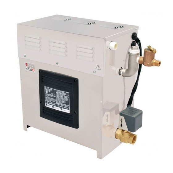
Page 4: Steam Generator Parts
Steam Generator Parts For illustrative purposes only. Terminal for Terminal for Contactor steam generator incoming line accessories Solenoid Valve Power switch Water Level Probe Transformer Steam Outlet Steam guard overflow Autodrain PCB cover Alternative Drain outlet For illustrative purposes only. Not for use for wiring. -
Page 5: Instructions Of Use
Instructions of Use There are four different operation modes in the unit: Off, On, Standby and Drain. The user can easily switch between different modes, making the steam bathing more convenient with less energy consumption. To use steam room the control unit needs to be in the On mode. In the On mode, the steamer is active, the temperature in the steam room will be kept in the preferred, set temperature, with occasional discharge of steam. -
Page 6: Standby Mode
Standby Mode During the standby-mode the water in the steam generator tank is kept hot. This minimizes the time to produce steam when generator goes to on-mode next time. Standby-mode can be activated by any of the following methods when the unit is in on-mode: Short press “Standby”... -
Page 7: Key Lock
Key Lock Lock and unlock the key pad by pressing the up and down buttons at the same time for more than 5 seconds. A high beep will confirm the activation and the deactivation. Only On/Off, Standby and Cabin light buttons are usable when the key pad is locked. -
Page 8: Scent Pump
Before switching scent pump on make sure there is enough aroma in the Scent Pump aroma container. Never run the scent pump dry. Scent pump can be operated in "On" mode only. In order to switch scent pump on/off short press “Fan/Scent” button. The Scent pump is allowed to be turned on only when the water in the tank is boiling. -
Page 9: Maintenance
They are connected to the water source of the steam generator’s water inlet. SAWO Decalcifying Solution can be used for decalcification. Follow these guidelines to perform preventative maintenance of the steam generator. -
Page 10: Level Probe Cleaning
2. Level probe cleaning Disconnect steam generator from main supply before opening generator’s covers. Only licenced electrician or professional maintence person can open covers and do cleaning. Use adjustable wrench to deattach 3 wires from level probe. Make sure that when connect- ing wires back, wires are connected to right probes Use adjustable wrench to remove level probe. -
Page 11: Assembly And Installation
Assembly and Installation Location of the steam generator has to be near the steam room. Place it within 7.5 meters to the steam room. Steam generator has to be installed outside the steam room. The steam generator must not be installed outdoors or areas that may damage the unit due to climate conditions. -
Page 12: Steam Generator
Steam Generator 3.0 kW | 3.5 kW | 4.0 kW | 4.5 kW | If facing the wall there should Side view 5.0 kW | 6.0 kW | 7.5 kW be atleast 100mm allowance. NOTE showing element access panel 540mm Water Inlet 3/4”... -
Page 13: Steam Outlet
Steam Outlet The steam must move in a continuous flow to the steam room. Do not istall valves on the steam line. Use insulated, rated 120ºC or higher, brass pipe or copper tubing for steam line to connect to the steam head as permitted by codes (see table below). Slope the steam line height by 20mm per meter towards the steam head to avoid trapping of the condensate and eliminate steam trap that blocks the flow of the steam. -
Page 14: Drain
Use two-wire supply source and equipment grounding wire of single phase connection. A 90ºC / 600V (HO7RN-F) rated insulated copper wire is required for SAWO steam generators. Check size of wires in Ampere Chart in accordance with the National Electrical Code and local electrical code. -
Page 15: Technical Data
Type Width Depth Height (kg) (kW) Number mm² (m³) 220 - 240 / 1N / STP-30-1/2 3 max 2 x 1.5 kW STG-150 380 - 415 220 - 240 / STP-35-1/2 3.5 3.5 max 1 x 1.5 kW STG-150 1N / 1 x 2.0 kW... - Page 16 CONVERTABLE POWER INPUT 380-415V 6.0 kW | 7.5 kW 220-240V TRANSFORMER GROUND WATER FEED SOLENOID VALVE 220-240V SWITCH 24VAC IN CONT. DRAIN FILL PROBE1 230VAC in PROBE2 PROBE3 FUSE CONTROL NTC2 TEMP BOARD CONTACTOR CONTACTOR SCENT PUMP LIGHT CONTROL HEATING ELEMENT NTC2 FUSE...
- Page 17 CONVERTABLE 9.0 kW 380-415V 220-240V TRANSFORMER GROUND WATER FEED SOLENOID VALVE 220-240V SWITCH 24VAC IN CONT. DRAIN FILL PROBE1 230VAC in PROBE2 PROBE3 FUSE CONTROL NTC2 TEMP BOARD CONTACTOR CONTACTOR SCENT PUMP LIGHT CONTROL HEATING ELEMENTS FUSE NTC2 AUTOMATIC DRAIN TEMP SENSOR 9.0 kW | 12.0 kW | 15.0 kW...
-
Page 18: Installing The Temperature Sensor
The temperature sensor comes along with the SAWO steam generator. It is recom- mended to use only Sawo temperature sensor with Sawo generator as it may other- wise not function correctly.Temperature sensor wiring should not be routed near power cables or hot areas as it may cause electronic interference or damage to the wires. -
Page 19: Installing Control Unit
Installing Control Unit SAWO Steam Control sets the temperature of your steam room. Mount the steam control unit on an accessible area outside the steam room. It is recommended not to place the steam control near to showers or similar wet places. -
Page 20: Connection Of Sawo
Connection of SAWO Control to the PCB. Before installation make sure that the generator is disconnected from the mains by switching off the circuit breaker Unscrew PCB cover on the side of the generator to get access on the PCB. -
Page 21: Terminal Connection Of
Terminal Connection of Demand Button (optional) Terminal Block Before installation make sure that the mains is disconnected from the generator by turning off the circuit breaker. 1. Open the top cover of the generator Guide the cable through cable lead-in on the side of the generator. -
Page 22: Dip Switches In The Steam Generator
DIP Switches in the Steam Generator FIRST BLOCK SECOND BLOCK STAND-BY ON/OFF Standby time Session Time Standby time can be set according to Session time can be set according to user user preferences setting preferences by session dip switches on the switches on the power controller board power controller board. -
Page 23: Steam Generator Series Connection
Steam Generator Series Connection Steam Generator Master Slave 1 Slave 2 Slave 3 Slave 4 Control Steam Generator Steam Generator Steam Generator DIP SW DIP SW DIP SW RJ12 Cable 3 = OFF 3 = ON 3 = ON 2 = OFF 2 = ON 1 = OFF 1 = OFF... - Page 24 No master steam generator Dip switch setting is incorrect. Check dip switch settings. connected Check RJ12 for loose contact. Replace RJ12. If no problem can be found, contact the retailer. www.sawo.com info@sawo.com Subject to change without notice.
Need help?
Do you have a question about the STP-30-1/2 and is the answer not in the manual?
Questions and answers