Advertisement
Quick Links
414435
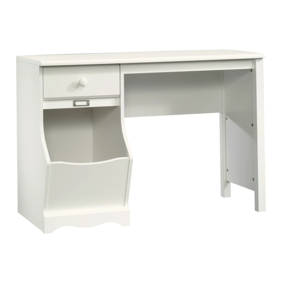
Desk
Pogo Collection
PLEASE CONTACT US
BEFORE RETURNING
YOUR UNIT TO THE STORE
1-800-523-3987
www.sauder.com
WARNING
CHOKING HAZARD - Small Parts
Not for children under 3 years.
NOTE: THIS INSTRUCTION BOOKLET CONTAINS
IMPORTANT SAFETY INFORMATION.
PLEASE READ AND KEEP FOR FUTURE REFERENCE.
Made in the USA
Archbold, OH
Lot #: 358785
Date Purchased: ____________________
English .................... Page 1-22
Français ...............Pages 23-25
Espanol .............Páginas 26-28
01 / 14 / 14
Advertisement

Subscribe to Our Youtube Channel
Related Manuals for Sauder Pogo 414435


Summary of Contents for Sauder Pogo 414435
- Page 1 PLEASE READ AND KEEP FOR FUTURE REFERENCE. BEFORE RETURNING English ....Page 1-22 YOUR UNIT TO THE STORE Français ....Pages 23-25 Made in the USA 1-800-523-3987 Espanol .....Páginas 26-28 Archbold, OH www.sauder.com Lot #: 358785 01 / 14 / 14 Date Purchased: ____________________...
- Page 2 ADULT ASSEMBLY REQUIRED Part Identifi cation .......3 ASSEMBLY TOOLS REQUIRED Hardware Identifi cation .....4 Assembly Steps ....5-22 No. 2 Phillips Screwdriver Français ......23-25 Tip Shown Actual Size Espanol ....... 26-28 Safety ......... 29-30 Hammer Warranty ........31 Page 2 www.sauder.com/services 414435...
-
Page 3: Part Identification
RIGHT END BACK RIGHT DRAWER SIDE LEFT END BRACE LEFT DRAWER SIDE FRONT LEG D705 DRAWER BOTTOM BOTTOM REAR LEG RAIL MODESTY PANEL BASE TOP MOLDING FRONT PANEL DRAWER FRONT SIDE PANEL DRAWER BACK D705 414435 www.sauder.com/services Page 3... -
Page 4: Hardware Identification
BLACK 1-1/8" PAN HEAD SCREW - 1 BLACK 1-9/16" FLAT HEAD SCREW - 4 BLACK 9/16" FLAT HEAD SCREW - 2 SILVER 3/8" MACHINE SCREW - 2 Screws are shown actual size. You may receive extra hardware with your unit. Page 4 www.sauder.com/services 414435... - Page 5 Look for this icon. It means a video assembly tip is available at: www.sauder.com/services/tips Do not tighten the HIDDEN CAMS in this step. Do not insert CAM DOWELS into these edges. Arrow Arrow (18 used) Insert the metal end of the CAM DOWEL into the HIDDEN CAM.
- Page 6 GOLD 5/16" FLAT HEAD SCREW (4 used in this step) Fasten the CABINET RIGHT (35DA) and CABINET LEFT (35DB) to the ENDS (A2 and B2). Use four GOLD 5/16" FLAT HEAD SCREWS (3S) through holes #1 and #3. Page 6 www.sauder.com/services 414435...
- Page 7 Flip the SIDE PANEL (G) over. Turn two BLACK 9/16" FLAT HEAD SCREWS (32S) into SIDE PANEL (G) until the shoulder of the SCREWS rest on the surface of it. Slide the BRACE (I) onto the SIDE PANEL (G). Line up the groove in the MOLDINGS over the head of the SCREWS in the SIDE PANEL. 414435 www.sauder.com/services Page 7...
- Page 8 Tighten Arrow Risk of damage or injury. Hidden Cams must be completely Arrow Maximum tightened. Hidden 210 degrees Cams that are not completely tightened Minimum may loosen, and parts 190 degrees may separate. To completely tighten: Page 8 www.sauder.com/services 414435...
- Page 9 Fill the hole in the TOP (C) 1/4 to 1/2 full with GLUE (8M). Flip the SIDE PANEL upside down and fasten the FRONT LEG (J) and SIDE PANEL (G) to the TOP (C). Tighten two HIDDEN CAMS. Wipe away the excess GLUE. 414435 www.sauder.com/services Page 9...
- Page 10 Finished edge F i n i s h S u r f a c Fasten the MODESTY PANEL (E) to the REAR LEG (K). Tighten two HIDDEN CAMS. Page 10 www.sauder.com/services 414435...
- Page 11 This hole must be here. S u r f a c H I D i t h Maximum Arrow 210 degrees Minimum 190 degrees Fasten the BOTTOM (D) to the RIGHT END (A2). Tighten two HIDDEN CAMS. 414435 www.sauder.com/services Page 11...
- Page 12 Next, fill the holes in the RIGHT END (A2) 1/4 to 1/2 full with GLUE (8M). Fasten the FRONT PANEL (F2) to the RIGHT END (A2). Push the WOOD DOWELS into the holes in the RIGHT END. Wipe away the excess GLUE. Page 12 www.sauder.com/services 414435...
- Page 13 Quickly, flip the LEFT END over and fasten it to the FRONT PANEL (F2) and BOTTOM (D). Wipe away the excess GLUE. Tighten two HIDDEN CONNECTORS in the BOTTOM. Fasten the LEFT END (B2) to the RAIL (R). Use a BROWN 7/16" LARGE HEAD SCREW (6S). 414435 www.sauder.com/services Page 13...
- Page 14 Curved edge Maximum Arrow 210 degrees Minimum 190 degrees Fasten the ENDS (A2 and B2) to the TOP (C). Tighten four HIDDEN CAMS. Page 14 www.sauder.com/services 414435...
- Page 15 Fasten the BASE (L) to the ENDS (A2 and B2) and BOTTOM (D). Use three BROWN 7/16" PAN HEAD SCREWS (6S). Fasten the RIGHT END (A) to the MODESTY PANEL (E). Use two BLACK 1-7/8" FLAT HEAD SCREWS (2S). 414435 www.sauder.com/services Page 15...
- Page 16 Fasten the TOP MOLDING (S) to the TOP (C). Use three BROWN 7/16" LARGE HEAD SCREWS (6S). NOTE: The TOP MOLDING does not have holes. Turn the screws into the groove of the MOLDING. Do not overtighten the screws. Page 16 www.sauder.com/services 414435...
- Page 17 Carefully turn your unit over onto its front edges. Lay the BACK (H) over your unit. Make equal margins along all four edges of the BACK (H). Push on opposite corners of your unit if needed to make it “square”. Fasten the BACK (H) to your unit using the NAILS (1N). 414435 www.sauder.com/services Page 17...
- Page 18 2. Slide the DRAWER BOTTOM (D705) into the grooves in the DRAWER SIDES (D83 and D84) and DRAWER FRONT (M). 3. Fasten the DRAWER BACK (D74) to the DRAWER SIDES (D83 and D84). Use four BLACK 1-9/16" LARGE HEAD SCREWS (30S). *U.S. Patent No. 6,413,007 Page 18 www.sauder.com/services 414435...
- Page 19 FLAT HEAD SCREWS (3S) through holes #1 and #3. NOTE: The screw head in the CAM must be visible through the slotted hole in the SLIDE. Fasten the KNOB (59K) to the DRAWER FRONT (M). Use a BLACK 1-1/8" PAN HEAD SCREW (9S). 414435 www.sauder.com/services Page 19...
- Page 20 Fasten a CARD HOLDER (21M) to the RAIL (R) as shown in the top diagram. Use two SILVER 3/8" MACHINE SCREWS (97S). Separate the CARDS on the CARD SHEET (40M) and insert one into the CARD HOLDER. Page 20 www.sauder.com/services 414435...
- Page 21 To insert the drawer into your unit, tip the front of the drawer down and drop the rollers on the drawer behind the rollers on the unit. Lift the front of the drawer up and slide it into the unit. 414435 www.sauder.com/services Page 21...
- Page 22 Tighten the SCREW when finished with adjustments. NOTE: Please read the back pages of the instruction booklet for important safety information. This completes assembly. To clean your unit, dampen a cloth with tap water and wipe. Page 22 www.sauder.com/services 414435...
-
Page 23: Liste De Pièces
VIS TÊTE GOUTTE DE SUIF D705 FOND DE TIROIR ......1 pour future référence. 28 mm NOIRE ........1 Pour contacter Sauder TRAVERSE ........1 30S VIS TÊTE PLATE 40 mm NOIRE ..4 en ce qui concerne cet MOULURE DE DESSUS ....1 élément, faire référence... - Page 24 Minimum de 190 degrés au PANNEAU AVANT (F2) et DESSOUS (D). Nettoyer l'excès de COLLE. Serrer deux EXCENTRIQUES ESCAMOTABLES dans le DESSOUS. Fixer l'EXTRÉMITÉ GAUCHE (B2) à la TRAVERSE (R). Utiliser une VIS TÊTE LARGE 11 mm MARRON (6S). Page 24 www.sauder.com/services 414435...
- Page 25 CÔTÉS DE TIROIR (D83 et D84) et du DEVANT DE TIROIR (M). 3. Fixer l'ARRIÈRE DE TIROIR (D74) aux CÔTÉS DE TIROIR (D83 et D84). Utiliser quatre VIS TÊTE LARGE 40 mm NOIRES (30S). * Brevet État Unis n° 6,413,007 414435 www.sauder.com/services Page 25...
-
Page 26: Lista De Partes
RIEL ..........1 TORNILLO NEGRO DE CABEZA en contacto con REDONDA de 28 mm .....1 MOLDURA DE PANEL Sauder en cuanto a SUPERIOR ........1 30S TORNILLO NEGRO DE CABEZA esta unidad, refi érase PERDIDA de 40 mm .......4 al número de lote y 35DA GABINETE DERECHO ....1... - Page 27 fi jarlo al PANEL DELANTERO (F2) y FONDO (D). Quite el exceso de PEGAMENTO. Apriete dos EXCÉNTRICOS ESCONDIDOS en el FONDO. Fije el EXTREMO IZQUIERDO (B2) al RIEL (R). Utilice un TORNILLO MARRON DE CABEZA GRANDE de 11 mm (6S). 414435 www.sauder.com/services Page 27...
- Page 28 CARA DE CAJÓN (M). 3. Fije el DORSO DE CAJÓN (D74) a los LADOS DE CAJÓN (D83 y D84). Utilice cuatro TORNILLOS NEGROS DE CABEZA GRANDE de 40 mm (30S). *Patente EE. UU. No. 6,413,007 Page 28 www.sauder.com/services 414435...
- Page 29 à mortelles. Les téléviseurs peuvent être un téléviseur. cet effet. particulièrement lourds. De plus, le poids et l’emplacement du tube image ont tendance à rendre les téléviseurs instables et enclins à tomber vers l’avant. 414435 www.sauder.com/services Page 29...
- Page 30 Además, el peso y la ubicación del tubo de imagen tienden a causar la inestabilidad de televisores y propensa a volcarse hacia adelante. Page 30 www.sauder.com/services 414435...
-
Page 31: Year Limited Warranty
4. La présente garantie ne s’applique qu’aux défauts garantis qui se produisent des composantes de mobilier Sauder. Le mot « défaut », tel qu’il est utilisé sous pour la première fois et qui sont signalés à Sauder dans les limites de ouverture les termes de la présente garantie, comprend les imperfections des pièces qui... - Page 32 Archbold, Ohio, where it all began. Manufactured by: Sauder Woodworking Company 502 Middle Street The Sauder name on the box ensures that Archbold, Ohio 43502 the item you have purchased is made with (419) 446-2711 the best quality workmanship and materials.
Need help?
Do you have a question about the Pogo 414435 and is the answer not in the manual?
Questions and answers