Advertisement
Available languages
Available languages
Quick Links
sauder.com
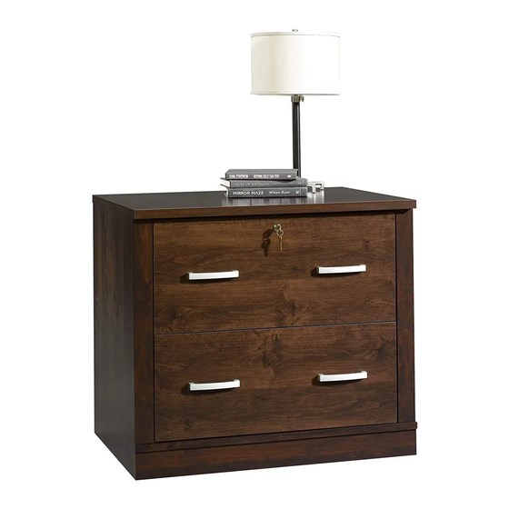
Lateral File
Offi ce Port Collection | Model 408293
Need help? Visit Sauder.com to view video assembly tips or chat with a live rep.
Prefer the phone? Call 1-800-523-3987.
Share your journey!
When you' r e feeling
nostalgic for paper.
NOTE: THIS INSTRUCTION
BOOKLET CONTAINS IMPORTANT
SAFETY INFORMATION.
PLEASE READ AND KEEP FOR
FUTURE REFERENCE.
English pg 1-25
Français pg 26-29
Español pg 30-33
Lot # 372756
05/20/15
Purchased: __________________
Be sure to give us a ring before
making any returns. 1-800-523-3987
Advertisement

Related Manuals for Sauder Office Port 408293


Summary of Contents for Sauder Office Port 408293
- Page 1 Offi ce Port Collection | Model 408293 NOTE: THIS INSTRUCTION BOOKLET CONTAINS IMPORTANT SAFETY INFORMATION. Need help? Visit Sauder.com to view video assembly tips or chat with a live rep. PLEASE READ AND KEEP FOR FUTURE REFERENCE. Prefer the phone? Call 1-800-523-3987.
- Page 2 D729 DRAWER BOTTOM (2) BOTTOM (1) EXTENSION BLOCK (4) BACK (1) INTERLOCK EXTENSION (1) BASE (1) BOTTOM MOLDING (1) UPPER DRAWER FRONT (1) END MOLDING (2) LOWER DRAWER FRONT (1) M63 BRACE (2) DRAWER BACK (2) Page 2 408293 www.sauder.com/services...
- Page 3 Use this part identifi cation to help identify similar parts. D729 D729 Hardware Identifi cation BACK FILE EXTENSION RAIL - 4 EXTENSION SLIDE - 4 FILE GLIDE - 4 HIDDEN CAM - 2 BRACKET - 2 (EXTENSION SET SHOWN SEPARATED) www.sauder.com/services 408293 Page 3...
- Page 4 30S BLACK 1-9/16" FLAT HEAD SCREW - 10 BLACK 1" PAN HEAD SCREW - 8 BLACK 9/16" LARGE HEAD SCREW - 8 BROWN 7/16" LARGE HEAD SCREW - 8 GOLD 5/16" FLAT HEAD SCREW - 16 NAIL - 26 Page 4 408293 www.sauder.com/services...
- Page 5 Assemble your unit on a carpeted fl oor or on the empty å carton to avoid scratching your unit or the fl oor. Some assembly To begin assembly, push a SAUDER TWIST-LOCK® (and snacks) required. å FASTENER (W) into the large holes in the RIGHT END (A) and LEFT END (B).
- Page 6 EXTENSION BLOCKS. The 1st hole must be 5 -1/2" from the end as shown. Follow the diagram closely. Edge with TWIST-LOCK® FASTENERS Notched edge Notched edge SILVER 2" FLAT HEAD SCREW (8 used for the EXTENSION BLOCKS) Page 6 408293 www.sauder.com/services...
- Page 7 Step 3 Fasten the INTERLOCKEXTENSION (N) to the RIGHT END (A). å Use two BROWN 1 -5/8" FLAT HEAD SCREWS (HH). BROWN 1-5/8” FLAT HEAD SCREW (2 used for the INTERLOCK EXTENSION) www.sauder.com/services 408293 Page 7...
- Page 8 Step 4 Insert two CABINET ACTUATORS (AA) into the holes å shown in the EXTENSION BLOCK (M). This pin must insert into the location holes in the EXTENSION BLOCK (M). Page 8 408293 www.sauder.com/services...
- Page 9 Do not use excessive force to open the drawers. Be sure the interlock track snaps into each cabinet actuator. Edge with TWIST-LOCK® FASTENERS Tape Measure www.sauder.com/services 408293 Page 9...
- Page 10 BLOCK. Turn a SCREW into this hole. Push the black lever in and pull the SLIDE from the RAIL. The CABINET Open end ACUATORS (AA) should be here. GOLD 5/16" FLAT HEAD SCREW (8 used in this step) Open end Page 10 408293 www.sauder.com/services...
- Page 11 Notched edge TWIST-LOCK® FASTENERS Notched edge Dowel end How to use the SAUDER TWIST-LOCK ® FASTENER 1. Insert the dowel end of the FASTENER into the hole of the adjoining part. NOTE: The dowel end of the FASTENER must remain fully inserted in the hole of the adjoining part while locking the FASTENER.
- Page 12 Step 8 Fasten the TOP (C) to the ENDS (A and B). Tighten four å TWIST-LOCK® FASTENERS. Unfi nished edge Page 12 408293 www.sauder.com/services...
- Page 13 ENDS (A and B). * U.S. Patent No. 5,499,886 å Notched edge Slide the END MOLDING (Z) onto the notched edge. Slide the END MOLDING (Z) onto the notched edge. These surfaces should be even. www.sauder.com/services 408293 Page 13...
- Page 14 Step 10 Fasten the BOTTOM MOLDING (O) to the BOTTOM (D). å Tighten three TWIST-LOCK® FASTENERS. These edges must be even. Page 14 408293 www.sauder.com/services...
- Page 15 NOTE: Be sure the BRACKETS are even with the edges of å the ENDS and BOTTOM. Fasten the BASE (F) to the METAL BRACKETS. Use four å BLACK 9/16" LARGE HEAD SCREWS (JJ). BLACK 9/16" LARGE HEAD SCREW (8 used in this step) www.sauder.com/services 408293 Page 15...
- Page 16 Do not stand the unit upright without the it "square". BACK fastened. The unit may collapse. Fasten the BACK (E) to your unit using the NAILS (MM). å Notched edge NAIL (26 used in this step) Page 16 408293 www.sauder.com/services...
- Page 17 Don't worry. It isn't each HIDDEN CAM. Rome. This can be built in a day. Do not tighten the HIDDEN CAMS in this step. Arrow Arrow Insert the metal end of the CAM DOWEL into the HIDDEN CAM. www.sauder.com/services 408293 Page 17...
- Page 18 Fasten the DRAWER BRACE (M63) to the UPPER å å SIDES (D87 and D88) and DRAWER BRACE (M63). Use DRAWER FRONT (G2). Tighten one HIDDEN CAM. five BLACK 1-9/16" FLAT HEAD SCREWS. (30S). Repeat this step for the other DRAWER. Page 18 408293 www.sauder.com/services...
- Page 19 Fasten one of the EXTENSION SLIDES (R) to the LEFT å DRAWER SIDE (D88). Use two GOLD 5/16" FLAT HEAD SCREWS (LL). (2 used) Open end GOLD 5/16" FLAT HEAD SCREW (4 used in this step) www.sauder.com/services 408293 Page 19...
- Page 20 These tabs must insert into the slots. å Screw head - turn CAM to line up the hole in the SLIDE with the hole in the DRAWER SIDE. (2 used) GOLD 5/16" FLAT HEAD SCREW (4 used in this step) Post Seated Page 20 408293 www.sauder.com/services...
- Page 21 Use four BLACK 1" PAN HEAD SCREWS (II). Repeat this step for the lower drawer. å BROWN 7/16" LARGE HEAD SCREW (8 used for the FILE BRACKETS) BLACK 1" PAN HEAD SCREW (8 used for the PULLS) www.sauder.com/services 408293 Page 21...
- Page 22 RIGHT DRAWER SIDE (D87). Slide another FILE GLIDE (6B) onto the other end of the å FILE RODS (U), then press this FILE GLIDE over the LEFT DRAWER SIDE (D88). Repeat this step for the lower drawer. å Page 22 408293 www.sauder.com/services...
- Page 23 The drawer will push in hard until it is all the way in, then it will slide in and out easier. 60 lbs. 45 lbs. 45 lbs. www.sauder.com/services 408293 Page 23...
- Page 24 The end of the CAM must be into the DRAWER FRONT closer to the DRAWER FRONT as you tighten the NUT then the other end of the CAM. with the adjustable wrench. Washer Screw Turn the key clockwise to lock the drawer. Page 24 408293 www.sauder.com/services...
- Page 25 #4. The higher the screw in the oblong hole, the higher your drawer front will be. The lower the screw, the lower the drawer front. www.sauder.com/services 408293 Page 25...
- Page 26 élément et conserver le livret pour future référence. EXTRÉMITÉ DROITE ..........1 FIXATION TWIST-LOCK® ........11 Pour contacter Sauder EXTRÉMITÉ GAUCHE ..........1 CONSOLE EN MÉTAL ..........4 en ce qui concerne cet DESSUS ................1 EXCENTRIQUE DE COULISSE ......4 élément, faire référence...
- Page 27 Pour commencer l'assemblage, enfoncer une FIXATION TWIST-LOCK® D'EXTENSION (M). Utiliser huit VIS DORÉES TÊTE PLATE 8 mm (LL). SAUDER (W) dans les gros trous de l'EXTRÉMITÉ DROITE (A) et l'EXTRÉMITÉ GAUCHE (B). Répéter cette étape pour le DESSOUS (D). REMARQUE : Pour chaque GLISSIÈRE D'EXTENSION, faire tourner une VIS dans le trou indiqué...
- Page 28 Utiliser quatre VIS NOIRES TÊTE GOUTTE DE SUIF 25 mm (II). Fixer l’ARRIÈRE DE TIROIR (D61) aux CÔTÉS DE TIROIR (D87 et D88) et à l’ENTRETOISE DE TIROIR (M63). Utiliser cinq VIS TÊTE PLATE Répéter cette étape pour le tiroir inférieur 40 mm NOIRES (30S). Page 28 408293 www.sauder.com/services...
- Page 29 Essuyer. soit complètement inséré. Le tiroir off rira une certaine résistance jusqu’à ce qu’il soit complètement inséré dans l’élément, il glissera ensuite sansdiffi culté. www.sauder.com/services 408293 Page 29...
- Page 30 EXCÉNTRICO DE CORREDERA .......4 et conserver le livret pour future référence. EXTREMO IZQUIERDO ............1 ACTUADOR DE GABINETE .........2 Pour contacter Sauder PANEL SUPERIOR ..............1 TIRADOR ................4 en ce qui concerne cet FONDO .................... 1 MÉNSULA DE ARCHIVERO ........2 élément, faire référence...
- Page 31 Fije dos RIELES DE EXTENSIÓN (Q) a cada BLOQUE DE Para comenzar el ensamblaje, empuje un SUJETADOR TWIST- EXTENSIÓN (M). Utilice ocho TORNILLOS DORADOS DE LOCK® SAUDER (W) dentro de los agujeros grandes del CABEZA PERDIDA de 8 mm (LL). EXTREMO DERECHO (A) y del EXTREMO IZQUIERDO (B). Repita este paso para el FONDO (D).
- Page 32 DE CAJÓN (D61). Utilice dos TORNILLOS MARRONES DE CABEZA GRANDE de 11 mm (KK). Fije dos TIRADORES (BB) a la CARA DE CAJÓN SUPERIOR (G2). Utilice cuatro TORNILLOS NEGROS DE CABEZA REDONDA de 25 mm (II). Repita este paso para el cajón inferior. Page 32 408293 www.sauder.com/services...
- Page 33 DE EXTENSIÓN sujetados a la unidad y empuje el cajón dentro de la unidad hasta que el cajón esté completamente insertado. El cajón mueve con difi cultad hasta que se inserte completamente dentro de la unidad, después deslizará fácilmente hacia dentroy hacia fuera. www.sauder.com/services 408293 Page 33...
- Page 34 Además, el peso y la un televisor. diseñadas para soportar un televisor. ubicación del tubo de imagen tienden a causar la inestabilidad de televisores y son propensos a inclinarse hacia adelante. Page 34 408293 www.sauder.com/services...
- Page 35 à compter de la date d'achat la première fois et qui sont signalés à Sauder dans les limites de couverture de la contre tout défaut de matériaux ou de fabrication des composantes de mobilier Sauder.
- Page 36 Dear Valued Customer: So, how did it go? Thanks so much for choosing Sauder® furniture. I hope the Set a world record for speed? purchase and assembly process was a positive experience Feeling good about yourself? and you feel good about the furniture you just built. If you Nice.