Table of Contents
Advertisement
Quick Links
CONTACT US FIRST
CONTACT US FIRST
sauder.com
sauder.com
sauder.com
BEFORE MAKING ANY RETURNS TO THE STORE.
BEFORE MAKING ANY RETURNS TO THE RETAILER.
sauder.com/service
Visit
Prefer the phone? Give us a ring at
Customer Service is available Monday-Friday - 9 a.m. to 5:30 p.m. EST (except holidays)
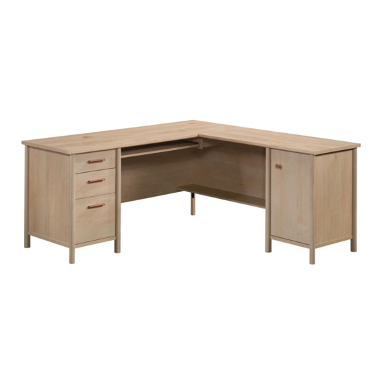
L-Shaped Desk
Whitaker Point Collection | Model 429368
Sauder.com
Share your journey!
to order replacement parts, view video assembly tips, or chat with a live rep.
1-800-445-1527
.
Business or pleasure.
Works both ways.
NOTE: THIS INSTRUCTION
BOOKLET CONTAINS IMPORTANT
SAFETY INFORMATION.
PLEASE READ AND KEEP FOR
FUTURE REFERENCE.
English pg 1-63
Français pg 64-71
Español pg 72-79
Lot # 573877
Purchased: __________________
11/16/21
Advertisement
Table of Contents

Related Manuals for Sauder Whitaker Point 429368


Summary of Contents for Sauder Whitaker Point 429368
- Page 1 CONTACT US FIRST CONTACT US FIRST sauder.com sauder.com sauder.com BEFORE MAKING ANY RETURNS TO THE STORE. BEFORE MAKING ANY RETURNS TO THE RETAILER. sauder.com/service Visit to order replacement parts, view video assembly tips, or chat with a live rep. 1-800-445-1527 Prefer the phone? Give us a ring at Customer Service is available Monday-Friday - 9 a.m.
-
Page 2: Table Of Contents
Table of Contents Assembly Tools Required Part Identification No. 2 Phillips Screwdriver Hardware Identification Tip Shown Actual Size Hardware Usage Guide Assembly Steps 7-63 Français 64-71 Español 72-79 Safety 80-82 Warranty Page 2 www.sauder.com/service 429368... -
Page 3: Part Identification
SMALL DRAWER FRONT (1) LARGE RIGHT DRAWER SIDE (1) LEFT RAIL SUPPORT (1) SMALL LEFT DRAWER SIDE (1) LARGE DRAWER BACK (1) GG RETURN BOTTOM (1) SMALL RIGHT DRAWER SIDE (1) LARGE DRAWER BOTTOM (1) HH BRACE (1) 429368 www.sauder.com/service Page 3... -
Page 4: Hardware Identification
DOOR STOP- 1 CAM - 70 CAM - 10 GROMMET PULL - 3 HINGE - 2 SHELF PIN - 4 WITH CAP- 2 KNOB - 1 PLATE - 2 CORNER BRACKET - 1 APPLIQUE CARD - 2 Page 4 www.sauder.com/service 429368... - Page 5 1/2" PAN HEAD SCREW - 10 1/2" MACHINE SCREW - 6 1" PAN HEAD SCREW - 6 3/4" PAN HEAD SCREW - 16 28 7/8" MACHINE SCREW - 1 1/2" FLAT HEAD SCREW - 4 1-1/8" FLAT HEAD SCREW - 2 429368 www.sauder.com/service Page 5...
-
Page 6: Hardware Usage Guide
The arrow in the HIDDEN CAM must point Arrow toward the hole in the edge of the board. Hidden Cam Hole Insert the CAM SCREW or CAM DOWEL into the HIDDEN CAM. Tighten the HIDDEN CAM. Page 6 www.sauder.com/service 429368... -
Page 7: Assembly Steps
Step 1 Look for this icon. It means a video assembly tip is available at www.sauder.com/service/tips Find the numbered video or scan the QR code. å Assemble your unit on a carpeted floor or on the empty carton to avoid scratching your unit or the floor. - Page 8 S u r f a c i t h H I D D E N D E N H I D i t h f a c S u r Page 8 www.sauder.com/service 429368...
- Page 9 Step 3 å Push four LARGE HIDDEN CAMS (9) into the LEFT DESK END (A). å Turn six CAM SCREWS (11) into the LEFT DESK END (A). Arrow 429368 www.sauder.com/service Page 9...
- Page 10 END. Turn a SCREW into these holes. å NOTE: The SMALL EXTENSION SLIDES will be used later for the DRAWERS. Push the black lever and pull the SLIDE from the RAIL. 3/8" FLAT HEAD SCREW (6 used in this step) Page 10 www.sauder.com/service 429368...
- Page 11 END. Turn a SCREW into these holes. å NOTE: The LARGE EXTENSION SLIDES will be used later for the DRAWERS. Push the black lever and pull the SLIDE from the RAIL. 3/8" FLAT HEAD SCREW (4 used in this step) Open end 429368 www.sauder.com/service Page 11...
- Page 12 Fasten the DESK BOTTOM (F) and BACK (H) to the LEFT DESK END (A). Tighten six HIDDEN CAMS. å NOTE: Be sure the WOOD DOWELS in the LEFT DESK END insert into the DESK BOTTOM and BACK. Page 12 www.sauder.com/service 429368...
- Page 13 Step 7 å Push four LARGE HIDDEN CAMS (9) into the RIGHT DESK END (C). å Turn six CAM SCREWS (11) into the RIGHT DESK END (C). Arrow 429368 www.sauder.com/service Page 13...
- Page 14 LARGE EXTENSION RAIL in to find the other holes that lines up with the holes in the RIGHT DESK END. Turn a SCREW into these holes. 3/8" FLAT HEAD SCREW (10 used in this step) Open end Page 14 www.sauder.com/service 429368...
- Page 15 Step 9 å Flip over the RIGHT DESK END (C). å Turn three CAM SCREWS (11) into the RIGHT DESK END (C). 429368 www.sauder.com/service Page 15...
- Page 16 Fasten the RIGHT DESK END (C) to the DESK BOTTOM (F) and BACK (H). Tighten six HIDDEN CAMS. å NOTE: Be sure the LARGE WOOD DOWELS in the RIGHT DESK END insert into the DESK BOTTOM and BACK. Page 16 www.sauder.com/service 429368...
- Page 17 Step 11 å Push ten LARGE HIDDEN CAMS (9) into the DESK MODESTY PANEL (G). å Turn ten CAM SCREWS (11) into the DESK MODESTY PANEL (G) and LEG (Z) as shown. Arrow Arrow Arrow 429368 www.sauder.com/service Page 17...
- Page 18 NOTE: Be sure the LARGE WOOD DOWELS in the RIGHT DESK END insert into the DESK MODESTY PANEL. Edge with holes These edges must be even. S u r f a c i t h H I D D E N Surface with CAM SCREWS Page 18 www.sauder.com/service 429368...
- Page 19 END (C). Use two 1-1/8" FLAT HEAD SCREWS (29). å NOTE: Be sure the LARGE WOOD DOWELS in the RIGHT DESK END insert into the LEFT RAIL SUPPORT. Surface with more holes Finished edge 1-1/8" FLAT HEAD SCREW (2 used in this step) 429368 www.sauder.com/service Page 19...
- Page 20 SMALL EXTENSION RAIL in to find the other holes that lines up with the holes in the LEFT RAIL SUPPORT. Turn a SCREW into these holes. Open end 3/8" FLAT HEAD SCREW (3 used in this step) Open end Page 20 www.sauder.com/service 429368...
- Page 21 Step 15 å Push ten LARGE HIDDEN CAMS (9) into the remaining BACK (H), and RETURN BOTTOM (GG). Arrow Arrow 429368 www.sauder.com/service Page 21...
- Page 22 S u r f a c i t h H I D D E N D E N H I D i t h f a c S u r Page 22 www.sauder.com/service 429368...
- Page 23 Push three LARGE HIDDEN CAMS (9) into the LEFT RETURN END (D). å Turn five CAM SCREWS (11) into the LEFT RETURN END (D). å Flip the LEFT RETURN END (D) over. å Turn five CAM SCREWS (11) into the LEFT RETURN END (D). Arrow 429368 www.sauder.com/service Page 23...
- Page 24 Fasten the BACK (H) and RETURN BOTTOM (GG) to the LEFT RETURN END (D). Tighten five HIDDEN CAMS. å NOTE: Be sure the LARGE WOOD DOWELS in the LEFT RETURN END insert into the BACK and RETURN BOTTOM. Page 24 www.sauder.com/service 429368...
- Page 25 Step 19 å Push three LARGE HIDDEN CAMS (9) into the RIGHT RETURN END (B). å Turn five CAM SCREWS (11) into the RIGHT RETURN END (B). Arrow 429368 www.sauder.com/service Page 25...
- Page 26 Fasten the RIGHT RETURN END (B) to the BACK (H) and RETURN BOTTOM (GG). Tighten five HIDDEN CAMS. å NOTE: Be sure the LARGE WOOD DOWELS in the RIGHT RETURN END insert into the BACK and RETURN BOTTOM. Page 26 www.sauder.com/service 429368...
- Page 27 Step 21 å Push nineteen LARGE HIDDEN CAMS (9) into the RETURN MODESTY PANEL (CC), and SHELF (DD). å Turn four CAM SCREWS (11) into the RETURN MODESTY PANEL (CC). Arrow Arrow Arrow Arrow Arrow Arrow 429368 www.sauder.com/service Page 27...
- Page 28 Fasten the SHELF (DD) to the RETURN MODESTY PANEL (CC). Tighten four HIDDEN CAMS. å NOTE: Be sure the LARGE WOOD DOWELS in the RETURN MODESTY PANEL insert into the SHELF. S u r f a c i t h H I D D E N Page 28 www.sauder.com/service 429368...
- Page 29 Fasten the RETURN MODESTY PANEL (CC) and SHELF (DD) to the DESK MODESTY PANEL (G). Tighten six HIDDEN CAMS. å NOTE: Be sure the LARGE WOOD DOWELS in the DESK MODESTY PANEL insert into the RETURN MODESTY PANEL and SHELF. (9 used) 429368 www.sauder.com/service Page 29...
- Page 30 Step 24 å Turn eighteen CAM SCREWS (11) into the DESK TOP (E). Page 30 www.sauder.com/service 429368...
- Page 31 Step 25 å Push five LARGE HIDDEN CAMS (9) into the RIGHT RAIL SUPPORT (BB), and BRACE (HH). Arrow 429368 www.sauder.com/service Page 31...
- Page 32 Fasten the RIGHT RAIL SUPPORT (BB) and BRACE (HH) to the DESK TOP (E). Tighten five HIDDEN CAMS. å NOTE: Be sure the LARGE WOOD DOWELS in the DESK TOP insert into the RIGHT RAIL SUPPORT and BRACE. Surface with HIDDEN CAMS Page 32 www.sauder.com/service 429368...
- Page 33 Step 27 å Fasten the RIGHT RAIL SUPPORT (BB) to the BRACE (HH). Use a 2" FLAT HEAD SCREW (21). 2" FLAT HEAD SCREW (1 used in this step) 429368 www.sauder.com/service Page 33...
- Page 34 EXTENSION RAIL in to find the other holes that lines up with the holes in the RIGHT RAIL SUPPORT. Turn a SCREW into these holes. 3/8" FLAT HEAD SCREW (3 used in this step) Open end Page 34 www.sauder.com/service 429368...
- Page 35 Step 29 å Turn eight CAM SCREWS (11) into the RETURN TOP (AA). Now might be a good time to refresh your drink. 429368 www.sauder.com/service Page 35...
- Page 36 Step 30 å Fasten the DOOR STOP (12) to the RETURN TOP (AA). Use two 1/2" PAN HEAD SCREWS (24). 1/2" PAN HEAD SCREW (2 used in this step) Page 36 www.sauder.com/service 429368...
- Page 37 MODESTY PANEL (CC). Tighten eight HIDDEN CAMS. å NOTE: Be sure the LARGE WOOD DOWELS in the RETURN TOP insert into the RETURN ENDS, BACK, and RETURN MODESTY PANEL. These holes must be here. (19 used) 429368 www.sauder.com/service Page 37...
- Page 38 Fasten the DESK MODESTY PANEL (G) to the RIGHT RAIL SUPPORT. Use two 2" FLAT HEAD SCREWS (21). å NOTE: You should start each SCREW a few turns before completely tightening any of them. 2" FLAT HEAD SCREW (2 used in this step) Page 38 www.sauder.com/service 429368...
- Page 39 Fasten the PLATES (18) to the TOPS (E and AA). Use sixteen 3/4" PAN HEAD SCREWS (27). å NOTE: You should start each SCREW a few turns before completely tightening any of them. 3/4" PAN HEAD SCREW (16 used in this step) 429368 www.sauder.com/service Page 39...
- Page 40 Fasten the CORNER BRACKET (19) to the MODESTY PANELS (G and CC) and LEG (Z). Use eight 1/2" PAN HEAD SCREWS (24). å NOTE: You should start each SCREW a few turns before completely tightening any of them. 1/2" PAN HEAD SCREW (8 used in this step) Page 40 www.sauder.com/service 429368...
- Page 41 RETURN ENDS (B and D). Set the ADJUSTABLE SHELF (X) onto the SHELF PINS. å Insert the GROMMETS WITH CAPS (14) into each large hole in the DESK TOP (E). (4 used) 429368 www.sauder.com/service Page 41...
-
Page 42: Machine Screw
å Fasten the KNOB (17) to the DOOR (Y). Use a 7/8" MACHINE SCREW (28). 1/2" FLAT HEAD SCREW (4 used in this step) 7/8" MACHINE SCREW (1 used in this step) Page 42 www.sauder.com/service 429368... - Page 43 Use the screws in the Adjusting HINGES. You should start each SCREW a few turns before screw completely tightening any of them. Hinge å See the next step for DOOR adjustments. 429368 www.sauder.com/service Page 43...
-
Page 44: Door Adjustments
To adjust the DOOR in or out (depth), loosen the mounting screw one turn and move the DOOR in or out, as needed. Tighten the mounting screw after making adjustments. Mounting screw (depth) Adjusting screw (horizontal) (vertical adjustment) Page 44 www.sauder.com/service 429368... - Page 45 Fasten the SMALL EXTENSION SLIDES (2) to the KEYBOARD SHELF (EE). Use six 1" PAN HEAD SCREWS (26) through the holes shown in the enlarged diagram. Open end 1" PAN HEAD SCREW (6 used in this step) Open end Open end Finished edge 429368 www.sauder.com/service Page 45...
- Page 46 Step Step 40 å Push four SMALL HIDDEN CAMS (10) into the LARGE DRAWER SIDES (T and U). Arrow Page 46 www.sauder.com/service 429368...
- Page 47 Fasten two LARGE EXTENSION SLIDES (4) to the LARGE DRAWER SIDES (T and U). Use six 3/8" FLAT HEAD SCREWS (23) through the holes shown in the enlarged diagram. Open end 3/8" FLAT HEAD SCREW (6 used in this step) Open end Open end 429368 www.sauder.com/service Page 47...
- Page 48 Step Step 42 å Turn four CAM SCREWS (11) into the LARGE DRAWER FRONT (S). Page 48 www.sauder.com/service 429368...
- Page 49 Fasten a PULL (16) to the LARGE DRAWER FRONT (S). Use two 1/2" MACHINE SCREWS (25). å NOTE: You should start each SCREW a few turns before completely tightening any of them. 1/2" MACHINE SCREW (2 used in this step) 429368 www.sauder.com/service Page 49...
- Page 50 Fasten the LARGE DRAWER FRONT (S) to the LARGE DRAWER SIDES (T and U). Tighten four HIDDEN CAMS. å NOTE: Be sure the DRAWER BOTTOM (W) inserts into the groove of the DRAWER FRONT (S). å NOTE: Be sure the WOOD DOWELS in the LARGE DRAWER FRONT insert into the LARGE DRAWER SIDES. Page 50 www.sauder.com/service 429368...
- Page 51 DRAWER SIDES (T and U). Hang your letter files on the FILE GLIDES (5) as shown. å Option 2: Place the FILE HANGERS (6) onto the FILE GLIDES (5). Hang your legal or letter files on the FILE HANGERS (6) as shown. Option 1 Option 2 429368 www.sauder.com/service Page 51...
- Page 52 Step 46 å Push four SMALL HIDDEN CAMS (10) into the DRAWER SIDES (P and Q). Arrow Page 52 www.sauder.com/service 429368...
- Page 53 Fasten two SMALL EXTENSION SLIDES (2) to the DRAWER SIDES (P and Q). Use six 3/8" FLAT HEAD SCREWS (23) through the holes shown in the enlarged diagram. Open end 3/8" FLAT HEAD SCREW (6 used in this step) Open end Open end 429368 www.sauder.com/service Page 53...
- Page 54 Step Step 48 å Turn four CAM SCREWS (11) into the DRAWER FRONT (O). Page 54 www.sauder.com/service 429368...
- Page 55 Fasten the PULL (16) to the DRAWER FRONT (O). Use two 1/2" MACHINE SCREWS (25). å NOTE: You should start each SCREW a few turns before completely tightening any of them. 1/2" MACHINE SCREW (2 used in this step) 429368 www.sauder.com/service Page 55...
- Page 56 Fasten the DRAWER FRONT (O) to the DRAWER SIDES (P and Q). Tighten four HIDDEN CAMS. å NOTE: Be sure the SMALL DRAWER BOTTOM (N) inserts into the groove of the DRAWER FRONT (O). å NOTE: Be sure the WOOD DOWELS in the DRAWER FRONT insert into the DRAWER SIDES. Page 56 www.sauder.com/service 429368...
- Page 57 Step Step 51 å Push two SMALL HIDDEN CAMS (10) into the SMALL DRAWER SIDES (K and L). Arrow 429368 www.sauder.com/service Page 57...
- Page 58 SMALL DRAWER SIDES (K and L). Use six 3/8" FLAT HEAD SCREWS (23) through the holes shown in the enlarged diagram. Open end 3/8" FLAT HEAD SCREW (6 used in this step) Open end Open end Page 58 www.sauder.com/service 429368...
- Page 59 Step Step 53 å Turn two CAM SCREWS (11) into the SMALL DRAWER FRONT (J). 429368 www.sauder.com/service Page 59...
- Page 60 Fasten the remaining PULL (16) to the SMALL DRAWER FRONT (J). Use two 1/2" MACHINE SCREWS (25). å NOTE: You should start each SCREW a few turns before completely tightening any of them. 1/2" MACHINE SCREW (2 used in this step) Page 60 www.sauder.com/service 429368...
- Page 61 Fasten the SMALL DRAWER FRONT (J) to the SMALL DRAWER SIDES (K and L). Tighten two HIDDEN CAMS. å NOTE: Be sure the DRAWER BOTTOM (N) inserts into the groove of the DRAWER FRONT (J). å NOTE: Be sure the WOOD DOWELS in the SMALL DRAWER FRONT insert into the SMALL DRAWER SIDES. 429368 www.sauder.com/service Page 61...
- Page 62 SHELF into the unit until the KEYBOARD SHELF is fully leave without a bite. inserted. The KEYBOARD SHELF will push in hard until it is all the way in, then it will slide in and out easier. Page 62 www.sauder.com/service 429368...
- Page 63 NOTE: Please read the back pages of the instruction booklet for important safety information. å This completes assembly. Clean with a damp cloth. Wipe dry. And to celebrate, why not share your success story at sauder.com or 10 lbs. 25 lbs.
-
Page 64: Liste De Pièces
DESCRIPTION QUANTITÉ REFERENCE DESCRIPTION QUANTITÉ conserver le livret pour future référence. Pour contacter Sauder en EXTRÉMITÉ GAUCHE DE BUREAU ....1 (ENSEMBLE DE PETITE GLISSIÈRE ILLUSTRÉ À PART) ce qui concerne cet EXTRÉMITÉ DROITE DE RETOUR....1 PETITE GLISSIÈRE D'EXTENSION ....6 élément, faire référence EXTRÉMITÉ... - Page 65 D'EXTENSION vers l'intérieur pour trouver les autres trous qui sont Faire tourner une VIS dans ces trous. alignés sur les trous dans l'EXTRÉMITÉ DROITE DE BUREAU. Faire REMARQUE : Les PETITES COULISSES D'EXTENSION seront tourner une VIS dans ces trous. utilisées ultérieurement pour les TIROIRS. 429368 www.sauder.com/service Page 65...
- Page 66 Fixer le VOILE DE FOND DE BUREAU (G) à l'EXTRÉMITÉ DROITE DE BUREAU (C). Serrer trois EXCENTRIQUES ESCAMOTABLES. REMARQUE : S’ a ssurer d’insérer les GRANDES CHEVILLES EN BOIS dans l’EXTRÉMITÉ DROITE DE BUREAU dans le VOILE DE FOND DE BUREAU. Page 66 www.sauder.com/service 429368...
- Page 67 REMARQUE : S’ a ssurer de bien insérer les GRANDES CHEVILLES DE RETOUR et la TABLETTE. EN BOIS de l’EXTRÉMITÉ DROITE DE RETOUR dans l'ARRIÈRE et le DESSOUS DE RETOUR. ÉTAPE 24 Faire tourner dix-huit VIS D'EXCENTRIQUE (11) dans le DESSUS DE BUREAU (E). 429368 www.sauder.com/service Page 67...
- Page 68 Fixer le VOILE DE FOND DE BUREAU (G) au SUPPORT DE RAIL DROIT. Utiliser deux VIS TÊTE PLATE 51 mm (21). REMARQUE : Il est préférable de donner quelques tours de tournevis à chaque VIS avant de les serrer toutes à bloc. Page 68 www.sauder.com/service 429368...
- Page 69 CLAVIER (EE). Utiliser six VIS TÊTE GOUTTE DE SUIF 25 mm (26) à travers les trous comme l'indique le schéma agrandi. ÉTAPE 40 Enfoncer quatre PETITES EXCENTRIQUES ESCAMOTABLES (10) dans les CÔTÉS DE GRAND TIROIR (T et U). 429368 www.sauder.com/service Page 69...
- Page 70 REMARQUE : S'assurer que le FOND DE TIROIR (W) s'encastre dans la rainure du DEVANT DE TIROIR (S). REMARQUE : S’ a ssurer d’insérer les CHEVILLES EN BOIS du DEVANT DE GRAND TIROIR dans les CÔTÉS DE GRAND TIROIR. Page 70 www.sauder.com/service 429368...
- Page 71 Fixer l’ a utre POIGNÉE (16) au DEVANT DE PETIT TIROIR (J). Utiliser deux VIS À MÉTAUX 13 mm (25). REMARQUE : Il est préférable de donner quelques tours de tournevis à chaque VIS avant de les serrer toutes à bloc. 429368 www.sauder.com/service Page 71...
-
Page 72: Lista De Partes
EXTREMO DERECHO DE MESA AUXILIAR ..1 necesita ponerse en RIEL DE EXTENSIÓN PEQUEÑO ....6 EXTREMO DERECHO DE ESCRITORIO ..1 contacto con Sauder en CORREDERA DE EXTENSIÓN PEQUEÑA ..6 EXTREMO IZQUIERDO DE MESA AUXILIAR..1 cuanto a esta unidad, (JUEGO DE EXTENSIÓN GRANDE SE PANEL SUPERIOR DE ESCRITORIO .....1... - Page 73 PLANA de 9,5 mm (23). que se alinean con los agujeros del EXTREMO IZQUIERDO DE ESCRITORIO. Atornille un TORNILLO dentro de estos agujeros. NOTA: La CORREDERA DE EXTENSIÓN PEQUEÑA se utilizará más tarde para los CAJONES. 429368 www.sauder.com/service Page 73...
- Page 74 Fije el VELO DE FONDO DE ESCRITORIO (G) al EXTREMO DERECHO DE ESCRITORIO (C). Apriete tres EXCÉNTRICOS ESCONDIDOS. NOTA: Asegúrese de que los PASADORES DE MADERA GRANDES del EXTREMO DERECHO DE ESCRITORIO se inserten en el VELO DE FONDO DE ESCRITORIO. Page 74 www.sauder.com/service 429368...
- Page 75 RIOSTRA (HH) al PANEL SUPERIOR DE ESCRITORIO (E). Apriete cinco EXCÉNTRICOS ESCONDIDOS. NOTA: Asegúrese de que los PASADORES DE MADERA GRANDES del PANEL SUPERIOR DE ESCRITORIO se inserten en el SOPORTE DE RIEL DERECHO y la RIOSTRA. 429368 www.sauder.com/service Page 75...
- Page 76 EXTREMOS DE MESA AUXILIAR (B y D). Coloque el ESTANTE AJUSTABLE (X) sobre las ESPIGAS DEL ESTANTE. Inserte los OJALES CON CUBIERTA (14) en cada agujero grande del PANEL SUPERIOR DE ESCRITORIO (E). Page 76 www.sauder.com/service 429368...
- Page 77 NOTA: Asegúrese de que los PASADORES DE MADERA de la CARA DE CAJÓN GRANDE se inserten en los LADOS DE CAJÓN GRANDE. REDONDA de 25 mm (26) a través los agujeros correspondientes indicados en el diagrama ampliado. 429368 www.sauder.com/service Page 77...
- Page 78 CARA DE CAJÓN se inserten en los LADOS DE CAJÓN. PASO 48 PASO 51 Atornille cuatro BIELAS DE EXCÉNTRICO (11) dentro de la CARA DE CAJÓN (O). Empuje dos EXCÉNTRICOS ESCONDIDOS PEQUEÑOS (10) en los LADOS DE CAJÓN PEQUEÑO (K y L). Page 78 www.sauder.com/service 429368...
- Page 79 CARA DE CAJÓN PEQUEÑO (J). Esto completa el ensamblaje. Limpiar con un trapo húmedo. Seque con un paño. Fije la CARA DE CAJÓN PEQUEÑO (J) a los LADOS DE CAJÓN PEQUEÑO (K y L). Apriete dos EXCÉNTRICOS ESCONDIDOS. 429368 www.sauder.com/service Page 79...
-
Page 80: Safety
• This product is not designed to support a not designed to support a television is heavy. Plus the weight and location of the television. hazardous. picture tube tends to make TVs unbalanced and prone to tipping forward. Page 80 www.sauder.com/service 429368... - Page 81 à Les téléviseurs peuvent être particulièrement un téléviseur. cet effet. lourds. De plus, le poids et l’emplacement du tube image ont tendance à rendre les téléviseurs instables et enclins à tomber vers l’ a vant. 429368 www.sauder.com/service Page 81...
- Page 82 Además, el peso y la ubicación del tubo de imagen tienden a causar la inestabilidad de televisores y propensa a volcarse hacia adelante. Page 82 www.sauder.com/service 429368...
-
Page 83: Year Limited Warranty
à compter de la date d'achat la première fois et qui sont signalés à Sauder dans les limites de couverture de la contre tout défaut de matériaux ou de fabrication des composantes de mobilier Sauder. - Page 84 BEFORE MAKING ANY RETURNS TO THE RETAILER. So, how did it go? Dear Valued Customer: Thanks so much for choosing Sauder® furniture. I hope the Set a world record for speed? purchase and assembly process was a positive experience Feeling good about yourself? and you feel good about the furniture you just built.
Need help?
Do you have a question about the Whitaker Point 429368 and is the answer not in the manual?
Questions and answers