Advertisement
Quick Links
CONTACT US FIRST
CONTACT US FIRST
sauder.com
sauder.com
sauder.com
BEFORE MAKING ANY RETURNS TO THE STORE.
BEFORE MAKING ANY RETURNS TO THE RETAILER.
sauder.com/service
Visit
Prefer the phone? Give us a ring at
Customer Service is available Monday-Friday - 9 a.m. to 5:30 p.m. EST (except holidays)
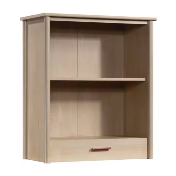
Library Hutch
Whitaker Point Collection | Model 429372
Sauder.com
Share your journey!
to order replacement parts, view video assembly tips, or chat with a live rep.
1-800-445-1527
.
Don't sweat the
small stuff anymore.
NOTE: THIS INSTRUCTION
BOOKLET CONTAINS IMPORTANT
SAFETY INFORMATION.
PLEASE READ AND KEEP FOR
FUTURE REFERENCE.
English pg 1-32
Français pg 33-36
Español pg 37-40
Lot # 573730
Purchased: __________________
11/16/21
Advertisement

Subscribe to Our Youtube Channel
Related Manuals for Sauder Whitaker Point 429372


Summary of Contents for Sauder Whitaker Point 429372
- Page 1 CONTACT US FIRST CONTACT US FIRST sauder.com sauder.com sauder.com BEFORE MAKING ANY RETURNS TO THE STORE. BEFORE MAKING ANY RETURNS TO THE RETAILER. sauder.com/service Visit to order replacement parts, view video assembly tips, or chat with a live rep. 1-800-445-1527 Prefer the phone? Give us a ring at Customer Service is available Monday-Friday - 9 a.m.
- Page 2 No. 2 Phillips Screwdriver Hardware Identification Tip Shown Actual Size Hardware Usage Guide Assembly Steps 6-32 Hammer Not actual size Français 33-36 Español 37-40 Pencil Safety 41-42 Electric drill with 1/8" or 3/8" bit (ONLY in indicated step) Warranty Page 2 www.sauder.com/service 429372...
- Page 3 LEFT BACK (1) RIGHT DRAWER SIDE (1) RIGHT END (1) RIGHT BACK (1) DRAWER BACK (1) TOP (1) MOLDING (1) DRAWER BOTTOM (1) BOTTOM (1) DRAWER FRONT (1) DRAWER BRACE (1) SHELF (1) LEFT DRAWER SIDE (1) 429372 www.sauder.com/service Page 3...
- Page 4 DOWEL - 3 2" FLAT HEAD SCREW - 4 1/2" MACHINE SCREW - 2 5/8" PAN HEAD SCREW - 12 1-1/2" FLAT HEAD SCREW - 3 3/8" FLAT HEAD SCREW - 12 1/2" PAN HEAD SCREW - 10 Page 4 www.sauder.com/service 429372...
- Page 5 The arrow in the HIDDEN CAM must point Arrow toward the hole in the edge of the board. Hidden Cam Hole Insert the CAM SCREW or CAM DOWEL into the HIDDEN CAM. Tighten the HIDDEN CAM. 429372 www.sauder.com/service Page 5...
- Page 6 Step 1 Look for this icon. It means a video assembly tip is available at www.sauder.com/service/tips Find the numbered video or scan the QR code. å Assemble your unit on a carpeted floor or on the empty carton to avoid scratching your unit or the floor.
- Page 7 Push the LEFT BACK (F) onto the LONG WOOD DOWELS (19) in the RIGHT BACK (G). S u r f a c i t h H I D D E N S u r f a c i t h H I D D E N 429372 www.sauder.com/service Page 7...
- Page 8 Step 3 å Push four LARGE HIDDEN CAMS (5) into the BOTTOM (D). Arrow Arrow Page 8 www.sauder.com/service 429372...
- Page 9 NOTE: Be sure the WOOD DOWELS in the BACKS insert into the BOTTOM. i t h f a c S u r D E N H I D 2" FLAT HEAD SCREW (4 used in this step) 429372 www.sauder.com/service Page 9...
- Page 10 Step 5 å Push two LARGE HIDDEN CAMS (5) into the LEFT END (A). å Turn five CAM SCREWS (7) into the LEFT END (A). Arrow Page 10 www.sauder.com/service 429372...
- Page 11 SCREW into these holes. å NOTE: The EXTENSION SLIDES will be used later for the DRAWERS. Push the black lever and pull the SLIDE from the RAIL. 3/8" FLAT HEAD SCREW (3 used in this step) Open end 429372 www.sauder.com/service Page 11...
- Page 12 Fasten the LEFT END (A) to the BOTTOM (D) and LEFT BACK (F). Tighten five HIDDEN CAMS. å NOTE: Be sure the LARGE WOOD DOWELS in the LEFT END insert into the BOTTOM and LEFT BACK. Page 12 www.sauder.com/service 429372...
- Page 13 Step Step 8 å Push two LARGE HIDDEN CAMS (5) into the RIGHT END (B). å Turn five CAM SCREWS (7) into the RIGHT END (B). Arrow 429372 www.sauder.com/service Page 13...
- Page 14 Then, slide the inner cartridge of the EXTENSION RAIL in to find the other holes that lines up with the holes in the RIGHT END. Turn a SCREW into these holes. 3/8" FLAT HEAD SCREW (3 used in this step) Open end Page 14 www.sauder.com/service 429372...
- Page 15 Fasten the RIGHT END (B) to the BOTTOM (D) and RIGHT BACK (G). Tighten five HIDDEN CAMS. å NOTE: Be sure the LARGE WOOD DOWELS in the RIGHT END insert into the BOTTOM and RIGHT BACK. 429372 www.sauder.com/service Page 15...
- Page 16 Step 11 å Turn six CAM SCREWS (7) into the TOP (C). Page 16 www.sauder.com/service 429372...
- Page 17 Step 12 å Insert two LARGE WOOD DOWELS (3) into the TOP (C). å Push the MOLDING (H) onto the LARGE WOOD DOWELS (3) in the TOP (C). Surface with holes 429372 www.sauder.com/service Page 17...
- Page 18 MOLDING (H). Use six 1/2" PAN HEAD SCREWS (18). Now might be a good time to refresh å NOTE: You should start each SCREW a few turns before your drink. completely tightening any of them. 1/2" PAN HEAD SCREW (6 used in this step) Page 18 www.sauder.com/service 429372...
- Page 19 Fasten the TOP (C) to the ENDS (A and B) and BACKS (F and G). Tighten four HIDDEN CAMS. å NOTE: Be sure the LARGE WOOD DOWELS in the TOP insert into the ENDS and BACKS. å NOTE: You will tighten the HIDDEN CAMS for the BACKS in the next step. (8 used) 429372 www.sauder.com/service Page 19...
- Page 20 Tighten two HIDDEN CAMS. your arms. å Open the FURNITURE TIPPING RESTRAINT KIT (96), and fasten the SAFETY STRAP to the TOP (C). Use the provided SHORT SCREW. Use the SHORT SCREW from the RESTRAINT KIT. SAFETY STRAP Page 20 www.sauder.com/service 429372...
- Page 21 Step 16 å Push three SMALL HIDDEN CAMS (6) into the DRAWER SIDES (K and L), and DRAWER BRACE (O). å Turn three CAM SCREWS (7) into the DRAWER FRONT (J). Arrow 429372 www.sauder.com/service Page 21...
- Page 22 Fasten the EXTENSION SLIDES (2) to the DRAWER SIDES (K and L). Use six 3/8" FLAT HEAD SCREWS (17) through the holes shown in the enlarged diagram. 3/8" FLAT HEAD SCREW (6 used in this step) Open end Open end Page 22 www.sauder.com/service 429372...
- Page 23 Step 18 å Fasten the PULL (11) to the DRAWER FRONT (J) as shown. Use two 1/2" MACHINE SCREWS (15). 1/2" MACHINE SCREW (2 used in this step) 429372 www.sauder.com/service Page 23...
- Page 24 BACK (M). Use a 1-1/2" FLAT HEAD SCREW (16). å NOTE: Be sure the WOOD DOWELS in the å NOTE: Be sure the WOOD DOWEL in the DRAWER DRAWER FRONT insert into the DRAWER BACK insert into the DRAWER BRACE. SIDES and DRAWER BRACE. Page 24 www.sauder.com/service 429372...
- Page 25 Step 20 å You have the option to have the Hutch on the 429373 or 429374. å This book will show you how to attach the Hutch to the 429373. 429372 www.sauder.com/service Page 25...
- Page 26 429373 top as shown in the enlarged diagram. Use twelve 5/8" PAN HEAD SCREWS (14). å NOTE: You should start each SCREW a few turns before completely tightening any of them. 5/8" PAN HEAD SCREW (12 used in this step) Page 26 www.sauder.com/service 429372...
- Page 27 429373 top. Use four 1/2" PAN HEAD SCREWS (18). å NOTE: You should start each SCREW a few turns before completely tightening any of them. 1/2" PAN HEAD SCREW (4 used in this step) 429372 www.sauder.com/service Page 27...
- Page 28 - Fasten the unit to the wall. Use the LONG SCREW through the other end of the SAFETY STRAP and into the 1/8" hole. Electric drill with 1/8" bit Mark and drill a 1/8" hole into the wall stud. Page 28 www.sauder.com/service 429372...
- Page 29 NOTE: You will need to turn the LONG SCREW multiple turns to completely tighten and secure your unit to the wall. Mark and drill a 3/8" hole Electric drill with 3/8" bit into the wall. Squeeze the wings together and tap the wall anchor into the 3/8" hole in the wall. 429372 www.sauder.com/service Page 29...
- Page 30 Step 25 å Insert the SHELF PINS (8) into the hole locations of your choice in the ENDS (A and B). Set the SHELF (E) onto the SHELF PINS. (4 used) Page 30 www.sauder.com/service 429372...
- Page 31 SLIDES on the drawer with the EXTENSION RAILS on the unit and push the drawer into the unit until the drawer is fully inserted. The drawer will push in hard until it is all the way in, then it will slide in and out easier. 429372 www.sauder.com/service Page 31...
- Page 32 NOTE: Please read the back pages of the instruction booklet for important safety information. å This completes assembly. Clean with a damp cloth. Wipe dry. And to celebrate, why not share your success story at sauder.com or 15 lbs. Page 32 www.sauder.com/service...
- Page 33 REFERENCE DESCRIPTION QUANTITÉ REFERENCE DESCRIPTION QUANTITÉ conserver le livret pour future référence. Pour contacter Sauder en EXTRÉMITÉ GAUCHE ..........1 (ENSEMBLE DE GLISSIÈRE ILLUSTRÉ À PART) ce qui concerne cet EXTRÉMITÉ DROITE ..........1 GLISSIÈRE D'EXTENSION ........2 élément, faire référence DESSUS ................1 COULISSE D'EXTENSION ........2...
- Page 34 ARRIÈRES (F et G). Fixer le DESSOUS (D) aux ARRIÈRES (F et G). Utiliser quatre VIS TÊTE PLATE 51 mm (13). REMARQUE : S’ a ssurer d’insérer les CHEVILLES EN BOIS des ARRIÈRES dans le DESSOUS. Page 34 www.sauder.com/service 429372...
- Page 35 Fixer trois CONSOLES EN MÉTAL (10) au DESSUS (C) et à la MOULURE (H). Utiliser six VIS TÊTE GOUTTE DE SUIF 13 mm (18). REMARQUE : Il est préférable de donner quelques tours de tournevis à chaque VIS avant de les serrer toutes à bloc. 429372 www.sauder.com/service Page 35...
- Page 36 429373. Utiliser quatre VIS TÊTE GOUTTE DE Ceci complète l'assemblage. Nettoyer avec un tissu humide. Essuyer. SUIF 13 mm (18). REMARQUE : Il est préférable de donner quelques tours de tournevis à chaque VIS avant de les serrer toutes à bloc. Page 36 www.sauder.com/service 429372...
- Page 37 EXTREMO IZQUIERDO ..........1 (JUEGO DE EXTENSIÓN SE MUESTRA POR su referencia futura. Si SEPARADO) necesita ponerse en EXTREMO DERECHO ..........1 contacto con Sauder en RIEL DE EXTENSIÓN ..........2 PANEL SUPERIOR ............1 cuanto a esta unidad, CORREDERA DE EXTENSIÓN ......2 FONDO .................1 refiérase al número...
- Page 38 Fije el FONDO (D) a los DORSOS (F y G). Utilice cuatro TORNILLOS DE CABEZA PLANA de 51 mm (13). NOTA: Asegúrese de que los PASADORES DE MADERA en los DORSOS se inserten en el FONDO. Page 38 www.sauder.com/service 429372...
- Page 39 Fije tres SOPORTES DE METAL (10) al PANEL SUPERIOR (C) y a la MOLDURA (H). Utilice seis TORNILLOS DE CABEZA REDONDA de 13 mm (18). NOTA: Debe apretar cada TORNILLO unas vueltas antes de apretar cualquier tornillo firmemente. 429372 www.sauder.com/service Page 39...
- Page 40 REDONDA de 13 mm (18). Esto completa el ensamblaje. Limpiar con un trapo húmedo. NOTA: Debe apretar cada TORNILLO unas vueltas antes de Seque con un paño. apretar cualquier tornillo firmemente. Page 40 www.sauder.com/service 429372...
- Page 41 Les téléviseurs peuvent être très lourds. De un téléviseur téléviseur. plus, le poids et l’emplacement du tube image ont tendance à rendre les téléviseurs instables et enclins à tomber vers l’ a vant. 429372 www.sauder.com/service Page 41...
- Page 42 El soportar un televisor. diseñadas para soportar un televisor. peso y la ubicación del tubo de imagen tienden a causar la inestabilidad de televisores y por eso tendrán la tendencia a inclinarse hacia adelante. Page 42 www.sauder.com/service 429372...
- Page 43 à compter de la date d'achat la première fois et qui sont signalés à Sauder dans les limites de couverture de la contre tout défaut de matériaux ou de fabrication des composantes de mobilier Sauder.
- Page 44 BEFORE MAKING ANY RETURNS TO THE RETAILER. So, how did it go? Dear Valued Customer: Thanks so much for choosing Sauder® furniture. I hope the Set a world record for speed? purchase and assembly process was a positive experience Feeling good about yourself? and you feel good about the furniture you just built.
Need help?
Do you have a question about the Whitaker Point 429372 and is the answer not in the manual?
Questions and answers