Table of Contents
Advertisement
Quick Links
414433
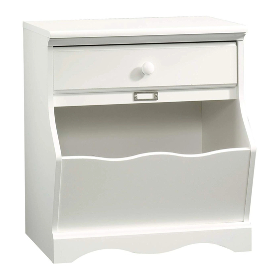
Nightstand
Pogo Collection
PLEASE CONTACT US
BEFORE RETURNING
YOUR UNIT TO THE STORE
1-800-523-3987
www.sauder.com
NOTE: THIS INSTRUCTION BOOKLET CONTAINS
IMPORTANT SAFETY INFORMATION.
PLEASE READ AND KEEP FOR FUTURE REFERENCE.
English .................... Page 1-15
Français ...............Pages 16-18
Made in the USA
Espanol .............Páginas 19-21
Archbold, OH
Lot #: 353017
Date Purchased: ____________________
05 / 08 / 13
Advertisement
Table of Contents

Subscribe to Our Youtube Channel
Related Manuals for Sauder Pogo 414433


Summary of Contents for Sauder Pogo 414433
- Page 1 PLEASE READ AND KEEP FOR FUTURE REFERENCE. BEFORE RETURNING English ....Page 1-15 YOUR UNIT TO THE STORE Français ....Pages 16-18 Made in the USA 1-800-523-3987 Espanol .....Páginas 19-21 Archbold, OH www.sauder.com Lot #: 353017 05 / 08 / 13 Date Purchased: ____________________...
- Page 2 TABLE OF CONTENTS ASSEMBLY TOOLS REQUIRED Part Identifi cation .......3 No. 2 Phillips Screwdriver Hardware Identifi cation .....4 Tip Shown Actual Size Assembly Steps ....5-15 Français ......16-18 Hammer Espanol ....... 19-21 Safety ........22 Warranty ........23 Page 2 www.sauder.com/services 414433...
-
Page 3: Part Identification
Use this PART IDENTIFICATION to help identify similar parts. RIGHT END FRONT PANEL D706 DRAWER BOTTOM LEFT END SKIRT RIGHT DRAWER SIDE RAIL LEFT DRAWER SIDE BOTTOM DRAWER FRONT DRAWER BACK TOP MOLDING BACK D706 414433 www.sauder.com/services Page 3... -
Page 4: Hardware Identification
BLACK 1-1/8" PAN HEAD SCREW - 1 BROWN 1-1/2" FLAT HEAD SCREW - 2 BLACK 1-9/16" FLAT HEAD SCREW - 4 SILVER 3/8" MACHINE SCREW - 2 Screws are shown actual size. You may receive extra hardware with your unit. Page 4 www.sauder.com/services 414433... - Page 5 Look for this icon. It means a video assembly tip is available at: www.sauder.com/services/tips Do not tighten the HIDDEN CAMS in this step. Arrow Arrow Insert the metal end of the CAM DOWEL into the HIDDEN CAM. (8 used) Assemble your unit on a carpeted fl oor or on the empty carton to avoid scratching your unit or the fl oor.
- Page 6 Fasten the CABINET RAILS (O and P) to the ENDS (A and B). Use four GOLD 5/16" FLAT HEAD SCREWS (3S) through holes #1 and #3. NOTE: The CABINET RAILS are marked "CABINET RIGHT" and "CABINET LEFT" for easy identification. Page 6 www.sauder.com/services 414433...
- Page 7 Tighten Arrow Risk of damage or injury. Hidden Cams must be completely Arrow Maximum tightened. Hidden 210 degrees Cams that are not completely tightened Minimum may loosen, and parts 190 degrees may separate. To completely tighten: 414433 www.sauder.com/services Page 7...
- Page 8 Next, fill the holes in the RIGHT END (A) 1/4 to 1/2 full with GLUE (8M). Fasten the FRONT PANEL (F) to the RIGHT END (A). Push the WOOD DOWELS into the holes in the RIGHT END. Wipe away the excess GLUE. Page 8 www.sauder.com/services 414433...
- Page 9 Quickly, flip the LEFT END over and fasten it to the FRONT PANEL (F) and BOTTOM (D). Wipe away the excess GLUE. Tighten two HIDDEN CONNECTORS in the BOTTOM. Fasten the LEFT END (B) to the RAIL (H). Use a BROWN 7/16" LARGE HEAD SCREW (6S). 414433 www.sauder.com/services Page 9...
- Page 10 NOTE: Be sure the BRACKETS are even with the edges of the BOTTOM and ENDS. Fasten the SKIRT (G) to the ENDS (A and B) and BOTTOM (D). Use three BROWN 7/16" PAN HEAD SCREWS (6S). Page 10 www.sauder.com/services 414433...
- Page 11 Make equal margins along all four edges of the BACK (J). Push on opposite corners of your unit if needed to make it “square”. Fasten the BACK (J) to your unit using the NAILS (1N). Tap four TACK GLIDES (12E) into the bottom edges of the ENDS (A and B). 414433 www.sauder.com/services Page 11...
- Page 12 2. Slide the DRAWER BOTTOM (D706) into the grooves in the DRAWER SIDES (D83 and D84) and DRAWER FRONT (I). 3. Fasten the DRAWER BACK (D85) to the DRAWER SIDES (D83 and D84). Use four BLACK 1-9/16" LARGE HEAD SCREWS (30S). *U.S. Patent No. 6,413,007 Page 12 www.sauder.com/services 414433...
- Page 13 NOTE: The DRAWER SLIDES are marked “DRAWER RIGHT” and “DRAWER LEFT” for easy identification. NOTE: The screw head in the CAM must be visible through the slotted hole in the SLIDE. Fasten the KNOB (59K) to the DRAWER FRONT (I). Use a BLACK 1-1/8" PAN HEAD SCREW (9S). 414433 www.sauder.com/services Page 13...
- Page 14 To insert the drawer into your unit, tip the front of the drawer down and drop the rollers on the drawer behind the rollers on the unit. Lift the front of the drawer up and slide it into the unit. Page 14 www.sauder.com/services 414433...
- Page 15 Tighten the SCREW when finished with adjustments. NOTE: Please read the back pages of the instruction booklet for important safety information. This completes assembly. To clean your unit, dampen a cloth with tap water and wipe. 414433 www.sauder.com/services Page 15...
-
Page 16: Liste De Pièces
14S VIS TÊTE PLATE 38 mm GLISSIÈRE GAUCHE pour future référence. MARRON .........2 D'ÉLÉMENT ........1 Pour contacter Sauder 30S VIS TÊTE PLATE 40 mm NOIRE ..4 COULISSE DROITE DE TIROIR ...1 en ce qui concerne cet 97S VIS À MÉTAUX 10 mm ARGENT ..2 élément, faire référence... - Page 17 TIROIR (D83 et D84). Utiliser quatre VIS TÊTE LARGE Fixer le PANNEAU AVANT (F) à l’EXTRÉMITÉ 40 mm NOIRES (30S). DROITE (A). Insérer les CHEVILLES EN BOIS dans les trous de l’EXTRÉMITÉ DROITE. Nettoyer l'excès de COLLE. * Brevet État Unis n° 6,413,007 414433 www.sauder.com/services Page 17...
- Page 18 REMARQUE : Prière de lire les informations importantes sur la sécurité fi gurant sur les pages arrière du manuel d’instructions. Ceci complète l'assemblage. Pour nettoyer l’unité, humidifi er un chiffon avec de l’eau du robinet et essuyer. Page 18 www.sauder.com/services 414433...
-
Page 19: Lista De Partes
CORREDERA DERECHA DE METAL de 10 mm ......2 CAJÓN ...........1 Si necesita ponerse en contacto con CORREDERA IZQUIERDA DE Sauder en cuanto a CAJÓN ...........1 esta unidad, refi érase EXCÉNTRICO DE CORREDERA ..2 al número de lote y al número de modelo TACHUELA DESLIZANTE .....4... - Page 20 NOTA: Asegúrese que los SOPORTES estén nivelados con los bordes del FONDO y de los EXTREMOS. Fije el FALDÓN (G) a los EXTREMOS (A y B) y al FONDO (D). Utilice tres TORNILLOS MARRONES DE CABEZA REDONDA de 11 mm (6S). Page 20 www.sauder.com/services 414433...
- Page 21 NOTA: La cabeza de tornillo del EXCÉNTRICO debe ser visible a través del agujero alargado de la CORREDERA. Fije el POMO (59K) a la CARA DE CAJÓN (I). Utilice un TORNILLO NEGRO DE CABEZA REDONDA de 28 mm (9S). 414433 www.sauder.com/services Page 21...
- Page 22 Además, el peso y la ubicación del tubo de imagen tienden a causar la inestabilidad de televisores y son propensos a inclinarse hacia adelante. Page 22 www.sauder.com/services 414433...
-
Page 23: Year Limited Warranty
4. La présente garantie ne s’applique qu’aux défauts garantis qui se produisent des composantes de mobilier Sauder. Le mot « défaut », tel qu’il est utilisé sous pour la première fois et qui sont signalés à Sauder dans les limites de ouverture les termes de la présente garantie, comprend les imperfections des pièces qui... - Page 24 Intended for Use by Children Under 8. (16 CFR 1500.49) still made in Archbold, Ohio, where it all began. Manufactured by: Sauder Woodworking Company The Sauder name on the box ensures that 502 Middle Street the item you have purchased is made with Archbold, Ohio 43502 (419) 446-2711 the best quality workmanship and materials.
Need help?
Do you have a question about the Pogo 414433 and is the answer not in the manual?
Questions and answers