
Related Manuals for HIS HIS-ML19.5-A Series


Summary of Contents for HIS HIS-ML19.5-A Series
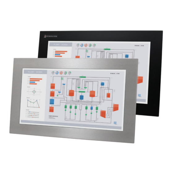
- Page 1 19.5" PANEL MOUNT INDUSTRIAL MONITOR REVISION A USER MANUAL Model No. HIS-ML19.5- _ _ _ A...
-
Page 2: Table Of Contents
Table of Contents Safety and Regulatory Information ��������������������������������������������������������������������������������3 FCC Notice ����������������������������������������������������������������������������������������������������������������������������� 3 Hazardous Locations �������������������������������������������������������������������������������������������������������������� 4 Waste Electrical and Electronic Equipment Directive (WEEE) ����������������������������������������������� 4 Mechanical Drawings ������������������������������������������������������������������������������������������������������5 Front and Side Views �������������������������������������������������������������������������������������������������������������� 5 Bottom View ���������������������������������������������������������������������������������������������������������������������������� 5 Rear View ������������������������������������������������������������������������������������������������������������������������������� 6 Installation Instructions ��������������������������������������������������������������������������������������������������7 Step 1: Prepare for Installation ����������������������������������������������������������������������������������������������... -
Page 3: Safety And Regulatory Information
Any changes or modifications not expressly approved by the grantee of this device could void the user’s authority to operate the device�... -
Page 4: Hazardous Locations
Safety and Regulatory Information Hazardous Locations This equipment is suitable for use in Class I, Division 2, Groups A, B, C, and D; Class II, Division 2, Groups F and G; Class III; or non-hazardous locations only� Device is open-type and is to be installed in an enclosure suitable for the environment that is only accessible with the use of a tool�... -
Page 5: Mechanical Drawings
Mechanical Drawings Mechanical Drawings Front and Side Views 527.0 mm (20.75") 241.3 mm 330.2 mm 267.7 mm (9.50") (13.00") (10.539") 437.4 mm (17.22") 7.1 mm (0.28") Bottom View 466.1 mm (18.349") 57.2 mm (2.25") (Design to maximum depth of 69.0 mm to ensure future compatibility with later revisions 7.1 mm and replacement units.) -
Page 6: Rear View
Mechanical Drawings Rear View 100 mm VESA Mounting Pattern (M4 screws provided, 16 mm maximum depth of screw) ML19.5A User Manual, 99158B, September 2021... -
Page 7: Installation Instructions
3� Ensure that the air temperature around the unit (top and bottom) will not exceed the rated specifications of the unit. f The maximum rated temperature for the HIS-ML19.5 is 50°C (122°F). f Remember that heat rises – the temperature at the top of the cabinet will be much hotter than at the bottom if air inside the enclosure is not actively circulating. -
Page 8: Step 2: Bench-Test Configuration
Installation Instructions Step 2: Bench-test Configuration Make sure everything works before installing into the production environment. TIP! If using a KVM extender, please refer to the installation instructions included with the KVM extender module. It is particularly important to bench-test the full configuration prior to final installation. - Page 9 Installation Instructions Video Connection The HIS-ML19.5 supports digital video through its DVI port, and analog video through its VGA port� After selecting the appropriate interface, connect one end of your video cable to the input port on the rear of the monitor and secure the screw locks to ensure adequate strain relief� Connect the other end to the appropriate port on your host computer or other video source�...
-
Page 10: Install Touch Screen Driver
Installation Instructions DC power input models are powered by 9�6 to 36�6 VDC, 2�5 to 0�65 A, Class 2 or SELV/LPS� 1� With main power disconnected, hook up incoming power wires to the DC input terminal blocks according to the label markings. Securely tighten terminal block screws�... - Page 11 Installation Instructions the bracket, route one end of the USB cable through the retention bracket and connect it to the USB input port on the monitor. Connect the other end to the USB port on the host computer� NOTE: If this step is not performed, the product will not comply with Class I, II, III, Division 2 Hazardous Location requirements.
-
Page 12: Step 3: Install Into Panel
Hope Industrial Systems will not assume liability for damage to internal electronics due to improper installation� Contact Hope Industrial Systems if you need additional assistance� 1� Refer to the drawing below for the cutout dimensions for the HIS-ML19.5. 497.8 mm (19.60") 298.5 mm... - Page 13 Installation Instructions 3� Cut a rectangular hole in the panel. f Cutout Dimensions (W x H) for the HIS-ML19.5: 497.8 mm x 298.5 mm (19.60" x 11.75"); ± 0.5 mm (0.020") 4� Clean and deburr the panel hole� 5� Separate the rear collar from the monitor by removing the 12 nuts.
-
Page 14: Video Settings
Video Settings Video Settings Setting the Timing Mode Setting the timing mode of your computer graphics adapter (or other video source) is important for maximizing the quality of the screen image and for minimizing eye strain. The timing mode consists of the resolution (e.g. 1920 x 1080) and refresh rate (or vertical frequency; e.g. 60 Hz). After setting the timing mode, use the On-Screen Display (OSD) controls to adjust the screen image. -
Page 15: Control Panel Buttons
Video Settings Control Panel Buttons Use the control panel buttons located on the back of the monitor to display and adjust various settings on the On-Screen Display (OSD) menu. CONTROL PANEL BUTTONS 1� To display the Main Menu, press button [1]. NOTE: All OSD menus and adjustment screens disappear automatically after 15 seconds. -
Page 16: Osd And Power Lock Settings
Video Settings Button Control Functions Enter When the OSD menu IS NOT displayed: • Shortcut to Auto Image Adjust. When the OSD menu IS displayed: • Displays the control screen for the highlighted control. Down / Blue Light When the OSD menu IS NOT displayed: Filter •... -
Page 17: On-Screen Display (Osd) Menus
Includes the Contrast and Brightness functions. Input Select Allows the user to toggle between inputs. Audio Adjust HIS-ML19.5 monitors do not include audio capabilities; these functions are inoperative for Hope Industrial monitors� Color Adjust Provides several color adjustment modes. Information Displays the timing mode (video signal input). -
Page 18: Auto Image Adjust Menu
Use D-Sub for analog VGA signals and DVI for digital signals. Audio Adjust Menu HIS-ML19.5 monitors do not include audio capabilities; these menu functions are inoperative for Hope Industrial monitors� ML19.5A User Manual, 99158B, September 2021... -
Page 19: Color Adjust Menu
Video Settings Color Adjust Menu The Color Adjust menu provides several color adjustment modes, including preset color temperatures and a User Color mode which allows independent adjustment of red (R), green (G), and blue (B). The factory setting for this product is Native. Color Adjust Menu Description sRGB... -
Page 20: Information Menu
Video Settings Information Menu The Information menu displays the timing mode (video signal input) coming from the graphics card in the computer. See your graphics card's user guide for instructions on changing the resolution and refresh rate (vertical frequency)� NOTE: VESA 1920 x 1080 @ 60 Hz (recommended) means that the resolution is 1920 x 1080 and the refresh rate is 60 Hz�... -
Page 21: Setup Menu
Video Settings Manual Image Adjust Description ECO Mode Provides lower power consumption by reducing the brightness. • Standard is the default brightness setting. • Optimize reduces brightness by 25%. • Conserve reduces brightness by 50%. View Mode Allows the user to select from five image modes to find the optimal screen setting for different applications, as well as the default "Standard"... -
Page 22: Memory Recall Menu
Video Settings Setup Menu Description Language Select Allows the user to choose the language used in the menus and control screens� Resolution Notice Advises the optimal resolution to use� OSD Position Allows the user to move the OSD menus and control screens� OSD Time Out Sets the length of time the OSD screen is displayed. -
Page 23: Cleaning Instructions
Cleaning Instructions Cleaning Instructions CAUTION! DO NOT USE ABRASIVE MATERIALS, SUCH AS PAPER TOWELS OR DIRTY SHOP RAGS, ON THE DISPLAY AS IT WILL SCRATCH THE PROTECTIVE COATING. ALWAYS USE A SOFT CLOTH, PREFERABLY MADE OF COTTON. All displays may be cleaned using any standard glass cleaner as long as there is no abrasive or oily content. -
Page 24: Troubleshooting
Troubleshooting Troubleshooting Video Troubleshooting IMPORTANT! If using a KVM extender, first try to resolve any problems using the solutions listed below. If the problem still exists, try bypassing the KVM extender. If this fixes the problem and allows the monitor to work properly, then the KVM extender is the source of the problem�... - Page 25 Troubleshooting Symptom Causes Solutions "Out of Range" The source signal exceeds Adjust the computer settings to the message box the maximum resolution monitor's native resolution: and no image on and/or refresh rate that the 1920 x 1080 @ 60 Hz the screen monitor can handle ( >...
-
Page 26: Touch Screen Troubleshooting
Troubleshooting Touch Screen Troubleshooting Applies to touch screen monitors only� To be sure that you have the most current driver, please check the following Internet address: https://www�HopeIndustrial�com/support/drivers/ Symptom Causes Solutions No response Touch screen driver has not Download and install the latest driver from when touching been installed�... -
Page 27: Specifications
Specifications Specifications Display Type Thin-film transistor (TFT) Active Matrix Liquid Crystal Size 19.5" diagonal Image Size (W x H) 434�88 mm x 238�68 mm (17�1" x 9�4") Native Resolution Full HD 1080p (1920 x 1080, 16:9 aspect ratio) Minimum Resolution VGA (640 x 480) Pixel Pitch 0�2265 mm x 0�221 mm... -
Page 28: Video
Specifications Video Input Connectors • HD-15, DVI-D • Compatible inputs using optional adapter (contact Hope Industrial Systems for details): • HDMI (via HDMI to DVI adapter) • DisplayPort (via DisplayPort to DVI adapter) • BNC (via HD-15 to 5-wire BNC adapter) Input Signal Formats •... -
Page 29: Electrical
Specifications Electrical Monitor Input • AC power models – 100 to 240 VAC, 1�5/0�75 A, 60/50 Hz • DC power models – 9�6 to 36�6 VDC, 2�5 to 0�65 A, Class 2 or SELV/LPS Power Consumption ~ 20 W Power Consumption <... -
Page 30: Compliances And Certifications
Specifications Compliances and Certifications Electrical • UL 60950 3 Edition / cUL Recognized Component (File No. E212889) • UL 508A Listed (File No. E318630) • FCC Class A • CAN ICES-3A/NMB-3A • • UKCA • NOM (Registration No. NOM-019-SCFI-1998) Environmental •... -
Page 31: Warranty Statement
Warranty Statement Warranty Statement Who is Covered? This warranty covers the purchaser of this product only and is not transferable without our written consent� What Does This Warranty Cover and What is the Period of Coverage? We warrant this product to be free from defects in material and workmanship, subject to the conditions set forth below. - Page 32 Hope Industrial Systems, Inc. US / International 1325 Northmeadow Parkway, Suite 100 Roswell, GA 30076 United States Toll Free: (877) 762-9790 | International: +1 (678) 762-9790 | Fax: +1 (678) 762-9789 Sales and Customer Service: sales@HopeIndustrial.com Support and Returns: support@HopeIndustrial.com Accounting Department: accounting@HopeIndustrial.com www.HopeIndustrial.com...