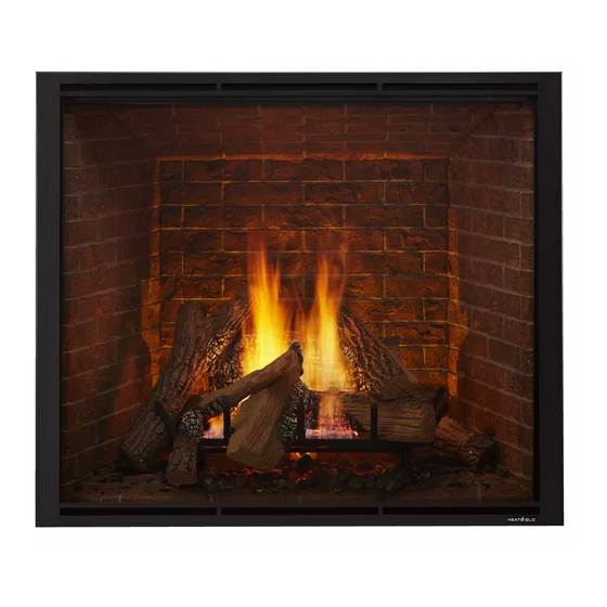
Table of Contents

Advertisement

Quick Links

INSTALLER: Leave this manual with party responsible for use and operation.
OWNER: Retain this manual for future reference.
NOTICE: DO NOT discard this manual!
Models:
TRUE-36G-IFT
TRUE-36TG-IFT
TRUE-36S-IFT
TRUE-42G-IFT
TRUE-42TG-IFT
TRUE-42S-IFT
TRUE-50TG-IFT
TRUE-50S-IFT
This appliance may be installed as an OEM
installation in manufactured home (USA
only) or mobile home and must be installed
in accordance with the manufacturer's
instructions and the Manufactured Home
Construction and Safety Standard, Title 24
CFR, Part 3280 in the United States, or the
Standard for Installation in Mobile Homes,
CAN/CSA Z240 MH Series, in Canada.
This appliance is only for use with the type(s)
of gas indicated on the rating plate. This
appliance is not convertible for use with other
gases, unless a certified kit is used.
Pour demander un exemplaire en français de ce Manuel du
propriétaire, visitez www.heatnglo.com/translations.
Heat & Glo • TRUE-36-IFT, TRUE-42-IFT, TRUE-50-IFT Installation Manual • 2461-980 Rev. Q • 11/20
Installation Manual
Installation and Appliance Setup
WARNING:
FIRE OR EXPLOSION HAZARD
Failure to follow safety warnings exactly
could result in serious injury, death, or
property damage.
• DO NOT store or use gasoline or other flam-
mable vapors and liquids in the vicinity of this
or any other appliance.
• What to do if you smell gas
- DO NOT try to light any appliance.
- DO NOT touch any electrical switch. DO
NOT use any phone in your building.
- Leave the building immediately.
- Immediately call your gas supplier from
a neighbor's phone. Follow the gas sup-
plier's instructions.
- If you cannot reach your gas supplier, call
the fire department.
• Installation and service must be performed
by a qualified installer, service agency, or the
gas supplier.
DANGER
DO NOT TOUCH GLASS
NEVER ALLOW CHILDREN
A barrier designed to reduce the risk of
burns from the hot viewing glass is provided
with this appliance and must be installed for
the protection of children and other at-risk
individuals.
In the Commonwealth of Massachusetts installation must be
performed by a licensed plumber or gas fitter.
See Table of Contents for location of additional Commonwealth
of Massachusetts requirements.
HOT GLASS WILL
CAUSE BURNS.
UNTIL COOLED.
TO TOUCH GLASS.
1

Advertisement

Table of Contents
loading
Need help?

Need help?

Do you have a question about the TRUE-36G-IFT and is the answer not in the manual?

Questions and answers

Subscribe to Our Youtube Channel

Summary of Contents for Heat&Glo TRUE-36G-IFT

  • Page 1 FIRE OR EXPLOSION HAZARD Failure to follow safety warnings exactly could result in serious injury, death, or Models: property damage. TRUE-36G-IFT • DO NOT store or use gasoline or other flam- TRUE-36TG-IFT mable vapors and liquids in the vicinity of this TRUE-36S-IFT or any other appliance.
  • Page 2: Table Of Contents

    D. Use of Elbows ....... . . 21 (TRUE-36G-IFT/TRUE-42G-IFT Only) ....55 E.
  • Page 3: Installation Standard Work Checklist

    Installation Standard Work Checklist ATTENTION INSTALLER: Follow this Standard Work Checklist This standard work checklist is to be used by the installer in conjunction with, not instead of, the instructions contained in this installation manual. Date Installed: Customer: Location of Fireplace: Lot/Address: Installer: Dealer/Distributor Phone #...
  • Page 4: Product Specific And Important Safety Information

    A. Appliance Certification D. High Altitude Installations NOTICE: If the heating value of the gas has been reduced, MODELS: TRUE-36G-IFT, TRUE-36TG-IFT, TRUE-36S-IFT, these rules do not apply. Check with your local gas utility TRUE-42G-IFT, TRUE-42TG-IFT, TRUE-42S-IFT or authorities having jurisdiction.
  • Page 5: Requirements For The Commonwealth Of Massachusetts

    Inspection Note: The following requirements reference various The state or local gas inspector of the side wall horizon- Massachusetts and national codes not contained in this tally vented gas fueled equipment shall not approve the document. installation unless, upon inspection, the inspector ob- serves carbon monoxide detectors and signage installed I.
  • Page 6: Getting Started

    Getting Started A. Design and Installation Considerations B. Good Faith Wall Surface Heat & Glo direct vent gas appliances are designed to operate with all combustion air siphoned from outside of CEILING the building and all exhaust gases expelled to the outside. 150°F FIREPLACE OPENING No additional outside air source is required.
  • Page 7: Inspect Appliance And Components

    D. Inspect Appliance and Components • Carefully remove the appliance and components from the packaging. • The vent system components and decorative fronts may be shipped in separate packages. • If packaged separately, the log set and appliance grate must be installed. •...
  • Page 8: Framing And Clearances

    Framing and Clearances A. Appliance/Decorative Front Dimension Diagrams Dimensions are actual appliance dimensions. Use for reference only. For framing dimensions and clearances refer to Section 5. APPLIANCE DIMENSION DIAGRAM (TRUE-36-IFT) HEAT-ZONE ® ® HEAT-ZONE PORT PORT S (diameter) ELECTRICAL ACCESS ACCESS Appliance Dimensions Table TRUE-36-IFT Location...
  • Page 9 APPLIANCE DIMENSION DIAGRAM (TRUE-42-IFT/TRUE-50-IFT) HEAT-ZONE ® HEAT-ZONE ® PORT PORT S (diameter) ELECTRICAL ACCESS Appliance Dimensions Table TRUE-42-IFT ACCESS Location Inches Millimeters Location Inches Millimeters 65-5/16 1659 1702 41-7/8 1064 45-7/8 1165 32-11/16 36-1/16 3-7/8 2-3/4 62-5/8 1591 10-7/8 40-13/16 1037 16-1/8 39-13/16...
  • Page 10 DECORATIVE FRONT DIMENSION DIAGRAM (TRUE-36-IFT) See Section 10 for facing and finishing detail. FS-36-IFT FS-36A-IFT 36-3/4 IN. (933 mm) 35-9/16 IN. 35-7/16 IN. 903 mm) 36-13/16 IN. (900 mm) (935 mm) 31-5/8 IN. (803 mm) 40-11/16 IN. 40-11/16 IN. (1033 mm) (1033 mm) 3-5/8 IN.
  • Page 11 DECORATIVE FRONT DIMENSION DIAGRAM (TRUE-42-IFT) See Section 10 for facing and finishing detail. FS-42-IFT FS-42A-IFT 41-13/16 IN. (1062 mm) 40-9/16 IN. 40-9/16 IN. (1030 mm) 41-13/16 IN. (1030 mm) (1062 mm) 36-3/4 IN. (934 mm) 46-11/16 IN. 46-11/16 IN. (1186 mm) (1186 mm) 3-9/16 IN.
  • Page 12 DECORATIVE FRONT DIMENSION DIAGRAM (TRUE-50-IFT) See Section 10 for facing and finishing detail. FS-50IFT FS-50AIFT 45-11/16 IN. (1161 mm) 44-7/16 IN. 44-7/16 IN. (1129 mm) 45-11/16 IN. (1129 mm) (1161mm) 40-5/8 IN. (1032 mm) 54-11/16 IN. 54-11/16 IN. (1389 mm) (1389 mm) 3-9/16 IN.
  • Page 13: Clearances To Combustibles

    NOTICE: Illustrations reflect typical installations and are B. Clearances to Combustibles FOR DESIGN PURPOSES ONLY. Illustrations/diagrams When selecting a location for the appliance it is important are not drawn to scale. Actual installation may vary due to to consider the required clearances to walls (see Figure individual design preference.
  • Page 14 Non-Combustible Zone 2 X 4 OR GREATER FRAMING MATERIAL 1/2 IN. BUILDING MATERIAL PIPE IS FOR VISUAL (MAY BE COMBUSTIBLE) REFERENCE ONLY NO COMBUSTIBLES IN HATCHED AREA 2 X 4 ONLY IN GRAY AREA NOTE: 2 X 4 HEADER CONFIGURATION 39 IN.
  • Page 15 (FROM APPLIANCE OPENING TO CEILING) NOTE: 2 X 4 Header positioned vertically. See also Figure 3.7. * MINIMUM FRAMING DIMENSIONS USING 2 X 4 CONSTRUCTION Rough Rough Rough Rough Sides of Clearance Combustible Combustible Behind Front of Opening Opening Opening Opening Appli- to Ceiling...
  • Page 16 2 X 6 OR GREATER NOT ALLOWED IN SHADED AREA (FROM APPLIANCE OPENING TO CEILING) B’ NOTE: 2 X 4 Header positioned vertically. See also Figure 3.7. * MINIMUM FRAMING DIMENSIONS USING 2 X 6 CONSTRUCTION B’ Rough Rough Rough Rough Clearance Opening...
  • Page 17: Constructing The Appliance Chase

    C. Constructing the Appliance Chase A chase is a vertical box-like structure built to enclose the gas appliance and/or its vent system. In cooler climates the vent should be enclosed inside the chase. NOTICE: Treatment of ceiling firestops and wall shield firestops and construction of the chase may vary with the type of building.
  • Page 18: Hearth Extension

    D. Hearth Extension NOTICE: DO NOT install a hearth that is greater than one inch thick. Hearth will interfere with installation of WARNING! Risk of Fire! Non-combustible hearth exten- glass assembly. Total hearth height must not exceed one sion may be required when appliance is installed on com- inch from bottom of appliance when appliance is installed bustible surface.
  • Page 19: Termination Location And Vent Information

    Termination Location and Vent Information A. Vent Termination Minimum Clearances 6 in. (minimum) up to 20 in. 18 in. minimum WARNING 152 mm/508 mm 457 mm 20 in. and over 0 in. minimum Fire Risk. Gas, Wood or Fuel Oil Maintain vent clearance to combustibles as Termination Cap specified.
  • Page 20: Chimney Diagram

    B. Chimney Diagram H or i Electrical Service = AREA WHERE TERMINAL IS NOT PERMITTED = VENT TERMINAL = AIR SUPPLY INLET Covered Alcove Applications = 12 inches....clearances above grade, veranda, porch, (Spaces open only on one side and with an overhang) deck or balcony TRUE-50 is not approved for use with vinyl siding or vinyl soffits.
  • Page 21: Approved Pipe

    C. Approved Pipe This appliance is approved for use with Hearth & Home Technologies DVP venting systems. Refer to Section 12.A for vent component information and dimensions. Only use listed decorative termination caps/shrouds with Hearth & Home Technologies approved venting systems. DO NOT mix pipe, fittings or joining methods from differ- ent manufacturers.
  • Page 22: Measuring Standards

    E. Measuring Standards Vertical and horizontal measurements listed in the vent diagrams were made using the following standards: • Pipe measurements are shown using the effective length of pipe. See Section 12.A (Figure 12.1) for information on effective length of pipe components. •...
  • Page 23: Vent Diagrams

    F. Vent Diagrams WARNING! Risk of Fire. This appliance requires a minimum of 24 inches of vertical venting before attaching any elbow to the appliance. DO NOT attach elbow directly to the appliance. General Rules: • This appliance is approved for use with Hearth & Home Technologies DVP venting systems ONLY. •...
  • Page 24 Two Elbows WARNING! Risk of Fire! • TRUE-36(NG/P),TRUE-42(NG/P) and TRUE-50(NG/P) models require a minimum of 36 inches of vertical venting before attaching any elbow to the appliance for the venting configuration in Figure 4.7. DO NOT attach elbow directly to the appliance. INSTALLED HORIZONTALLY TRUE-36 (NG/P), TRUE-42 (NG/P),...
  • Page 25 Top Vent - Horizontal Termination - (continued) Three Elbows WARNING! Risk of Fire! • TRUE-36(NG/P), TRUE-42(NG/P) and TRUE-50 (NG/P) models require a minimum of 24 inches of vertical venting before attaching any elbow to the appliance. DO NOT attach elbow directly to the appliance. TRUE-36 (NG/P), TRUE-42 (NG/P), TRUE-50 (NG/P) Minimum Maximum...
  • Page 26 Top Vent - Vertical Termination No Elbow = 50 ft. Max. (15.2 m) = 2 ft. Min. (610 mm) Figure 4.11 Heat & Glo • TRUE-36-IFT, TRUE-42-IFT, TRUE-50-IFT Installation Manual • 2461-980 Rev. Q • 11/20...
  • Page 27 Exhaust Restrictor Instructions Exhaust restrictors are recommended for these vertically terminated products which have excessive draft. Exhaust restrictors will compensate for high draft, and restore vi- sual flame height. If the vent configuration has a total ver- tical of 11-50 feet, an exhaust restrictor may be needed. BREAK The exhaust restrictor can be located in the appliance HERE...
  • Page 28 Top Vent - Vertical Termination - (continued) 2 ELBOWS TRUE-36 (NG/P), TRUE-42 (NG/P), TRUE-50 (NG/P) WARNING! Risk of Fire! Minumum Maximum • TRUE-36(NG/P), TRUE-42(NG/P) and TRUE-50 (NG/P) models 2 ft 610 mm 1 ft 305 mm require a minimum of 24 inches of vertical venting before attaching 3 ft 914 mm 3 ft...
  • Page 29 Top Vent - Vertical Termination - (continued) Three Elbows TRUE-36 (NG/P), TRUE-42 (NG/P), TRUE-50 (NG/P) Minimum Max. WARNING! Risk of Fire! TOTAL 2 ft 610 mm 7 in 178 mm • TRUE-36(NG/P), TRUE-42(NG/P) and TRUE-50 (NG/P) 3 ft 914 mm 2 ft 610 mm models require a minimum of 24 inches of vertical venting...
  • Page 30: Pvlp-Slp And Pvi-Slp-B Information

    PVI-SLP-B: The baffle adjustment is measured using the G. PVLP-SLP and PVI-SLP-B Information holes on the indicator bar of the PVI-SLP-B baffle. This bar raises as the baffle is opened and lowers as the baffle This section provides specific detail for installation of is closed.
  • Page 31: Vent Clearances And Framing

    Vent Clearances and Framing A. Pipe Clearances to Combustibles Non-Combustible Wall Penetration If the hole being penetrated is surrounded by non-com- WARNING! Risk of Fire! Maintain air space clearance bustible materials such as concrete, a hole with diameter to vent. DO NOT pack insulation or other combustibles: one inch greater than the pipe is acceptable.
  • Page 32: Ceiling Firestop/Floor Penetration Framing

    C. Ceiling Firestop/Floor Penetra- tion Framing A ceiling firestop MUST be used between floors and attics. • DVP pipe only - Frame an opening 10 in. by 10 in. (254 mm by 254 mm) whenever the vent penetrates a ceiling/floor (see ATTIC ABOVE Figure 5.3).
  • Page 33: Prepare For Heat Management

    E. Prepare for Heat Management • Locate the heat management knockouts on the left and right sides of the appliance. See Figure 5.5. Remove one of the knockouts from the appliance with a tin snips. • Center the duct collar around the exposed hole and attach it to the appliance with 3 screws.
  • Page 34: Appliance Preparation

    (Section 6), splatter guard and finishing templates SEAL CAP SEAL CAP (Section 10), and the logs and Teco-Sil (Section 11). For TRUE-36G-IFT and TRUE-42G-IFT models, the glass refractory is also shipped with the appliance. See Figure 6.1. NOTE: Header heat shields and finish trim on TRUE-G models are attached to appliance on the rear corner and must be removed using a 1/4 inch nut driver.
  • Page 35: Securing And Leveling The Appliance

    Figure 6.4 Side Nailing Tab in Shipping Position Figure 6.3. Shipping Location of Header Heat Shields and Finish Trim Pieces - TRUE-36G-IFT and TRUE-42G-IFT B. Securing and Leveling the Appliance WARNING! Risk of Fire! Prevent contact with: • Sagging or loose insulation •...
  • Page 36: Installing Non-Combustible Facing Material

    C. Installing Non-Combustible Facing Material WARNING! Risk of Fire! • Follow these instructions exactly. • Facing materials must be installed properly to prevent fire. PERIMETER: SECURE TO FRAMING WITH • No materials may be substituted without authorization DRYWALL SCREWS OR NAILS (NOT INCLUDED) by Hearth &...
  • Page 37: Venting And Chimneys

    Venting and Chimneys A. Assemble Vent Sections Attach Vent to the Firebox Assembly Note: The end of the pipe sections with the lanced tabs will face toward the appliance. Attach the first pipe section to the starting collar: • Lanced pipe end of the starting collar. •...
  • Page 38: Secure The Vent Sections

    B. Secure the Vent Sections C. Disassemble Vent Sections • Vertical runs originating off the top of the appliance, with • Rotate either section (see Figure 7.7) so the seams on no offsets, must be supported every 8 ft. (2.44 m) after both pipe sections are aligned as shown in Figure 7.8.
  • Page 39: Vertical Termination Requirements

    NOTICE: Failure to properly caulk the roof flashing and D. Vertical Termination Requirements pipe seams could permit entry of water. Install Metal Roof Flashing • Caulk the gap between the roof flashing and the outside • See minimum vent heights for various pitched roofs diameter of the pipe.
  • Page 40: Horizontal Termination Requirements

    • The extended heat shield may need to be cut to length Install Vertical Termination Cap maintaining sufficient length for a 1-1/2 in. (38 mm) • Attach the vertical termination cap by sliding the inner overlap between heat shields. collar of the cap into the inner flue of the pipe section •...
  • Page 41: Electrical Information

    Electrical Information Junction Box Installation A. General Information The electrical junction box can be accessed three ways WARNING! Risk of Shock or Explosion! DO NOT wire during installation: 110-120 VAC to the valve or to the appliance wall switch. 1. Through the side electrical access: Incorrect wiring will damage controls.
  • Page 42 NOTICE: DO NOT wire 110-120 VAC to wall switch. Romex Connector 14/2WG GRN wire inside box Copper ground attached to GRN screw with GRN wire Figure 8.2 Junction Box Detail Accessories Requirements • This appliance may be used with a wall switch, wall mounted thermostat and/or a remote control.
  • Page 43: Wiring Requirements

    • Plug the 6 volt transformer plug into the appliance junction B. Wiring Requirements box to supply power to the unit OR install 4 AA cell ® IntelliFire Touch Ignition System Wiring batteries (not included) into the battery pack before use. •...
  • Page 44: Gas Information

    Gas Information A. Fuel Conversion C. Gas Connection • Make sure the appliance is compatible with available gas • Refer to Section 3 for location of gas line access in types. appliance. • Conversions must be made by a qualified service •...
  • Page 45: Air Shutter Setting

    E. Air Shutter Setting Air shutter settings should be adjusted by a qualified ser- vice technician at the time of installation. The air shutter is pre-set at the factory for minimum vertical, maximum horizontal vent run for this appliance: 2 ft. vertical and 7 in.
  • Page 46: Finishing

    Finishing A. Facing Material • Metal front faces may be covered with non-combustible materials only. • Facing and/or finishing materials must not interfere with air flow through louvers, operation of louvers or decorative fronts, or access for service. • Facing and/or finishing materials must never overhang into the glass opening.
  • Page 47: Finishing Templates

    B. Finishing Templates Two side finishing templates and one top finishing template are supplied with the appliance. Refer to the decorative front instructions for template removal. 3/4 IN. INSIDE FIT Method: The finishing template pieces are required for installations that require more than one inch thick finishing materials to be installed over the face of the factory-supplied 1/2 inch non-combustible board.
  • Page 48 Figure 10.5 Finishing Template Bends Heat & Glo • TRUE-36-IFT, TRUE-42-IFT, TRUE-50-IFT Installation Manual • 2461-980 Rev. Q • 11/20...
  • Page 49: Mantel And Wall Projections

    C. Mantel and Wall Projections Non-Combustible Zone WARNING! Risk of Fire! Comply with all minimum clear- ances as specified. Framing closer than the minimums list- 2 X 4 OR GREATER FRAMING MATERIAL ed must be constructed entirely of non-combustible materi- als (i.e., steel studs, concrete board, etc.).
  • Page 50 Combustible Mantel Projections - TRUE-42 Non-Combustible Mantel Projections - TRUE-36 1/2 IN. NON-COMBUSTIBLE 1/2 IN. MATERIAL NON-COMBUSTIBLE MAX. Note: All measurements in inches. MAX. MATERIAL Note: Measurement is taken Note:All measurements in inches. from bottom of appliance. Note: Measurement is taken from bottom of appliance.
  • Page 51: Decorative Front Dimensions For Finishing

    The decorative fronts approved for use with this appli- Non-Combustible Mantel Projections - TRUE-50 ance have been designed to be installed by two methods: Overlap Fit or Inside Fit. Before beginning the installation, it is important to determine with method will be used. 1/2 IN.
  • Page 52: Appliance Setup

    11 11 Appliance Setup A. Fixed Glass Assembly WARNING! Risk of Asphyxiation! Handle fixed glass assembly with care. Inspect the gasket to ensure it is undamaged and inspect the glass for cracks, chips or scratches. • DO NOT strike, slam or scratch glass. •...
  • Page 53 Once the glass is installed tightly into the top retainer Replacing Fixed Glass Assembly rail, push in the bottom so that the glass assembly This fixed glass assembly is held in place by two side rests on the support tabs on the glass clip. See Fig- clips, one top retaining rail and lower glass clips.
  • Page 54: Remove The Shipping Materials

    B. Remove the Shipping Materials C. Clean the Appliance Clean/vacuum any sawdust that may have accumulated Remove shipping materials from inside or underneath inside the firebox or underneath in the control cavity. the firebox. • The splatter guard is a piece of corrugated material used to protect the appliance during the installation process before finishing work on the whole hearth is complete.
  • Page 55: Install Glass Refractory (True-36G-Ift/True-42G-Ift Only)

    2. Carefully remove top refractory by straightening the D. Install Glass Refractory (TRUE-36G-IFT/ retaining tabs. Set refractory panel aside for later TRUE-42G-IFT Only) use. See Figure 11.9. 3. Separate the shipping bracket from the log grate by CAUTION! Risk of Cuts or Abrasions. Wear protective cutting the zip tie with a utility knife.
  • Page 56 BEND TABS TO RETAIN GLASS BEND TABS TO RETAIN GLASS BEND TABS BEND TABS LEFT SIDE SPACER LEFT SIDE SPACER Figure 11.12 Left Refractory Tab Figure 11.14 Left Refractory Tab 7. Place back glass panel with arched portion down into the rear of the appliance.
  • Page 57 APPLY PRESSURE TO THIS EDGE APPLY PRESSURE TO THIS EDGE Figure 11.18 Top Refractory Placement Figure 11.17 Lower Right Finish Trim 11. Carefully reinstall base refractory, removed in step 5, back into position. Refer to Figure 11.9 for correct placement. 12.
  • Page 58: Install Teco-Sil And Mystic Embers

    E. Install Teco-Sil and Mystic Embers 1. Install Teco-Sil along front edge of glass as shown in Figure 11.19. Rock should follow contour cutout in the front refractory. Figure 11.21. Teco-Sil Painted 4. Apply Mystic Embers around the ember bed and hearth refractory.
  • Page 59: Glowing Ember Placement

    G. LED’s F. Glowing Ember Placement LED’s are factory installed. No additional set up or acti- WARNING! Risk of Explosion! Follow ember placement vation required. instructions in manual. DO NOT place embers directly over burner ports. Replace ember material annually. Improperly •...
  • Page 60: Install The Log Assembly

    LOG PLACEMENT INSTRUCTIONS H. Install the Log Assembly Log Set Assembly: LOGS-TRUE36 LOGS-TRUE42 Models: TRUE-36C, TRUE-36H, TRUE-36S, TRUE-36G-IFT, TRUE-36H-IFT, TRUE-36S-IFT, TRUE-36TG-IFT TRUE-42C, TRUE-42H, TRUE-42S, TRUE-42G-IFT, TRUE-42H-IFT, TRUE-42S-IFT, TRUE-42TG-IFT Note: Refractory appearance and material will vary depending on fireplace model. LOG PLACEMENT TABS...
  • Page 61 LOG #5 APPEARANCE LOG #5 APPEARANCE NOTCH NOTCH VARIES SLIGHTLY VARIES SLIGHTLY BETWEEN MODELS BETWEEN MODELS TOP OF BURNED TOP OF BURNED AREA NEAR LOG #1 AREA NEAR LOG #1 LEFT LEFT LOG RESTING IN NOTCH LOG RESTING IN NOTCH RIGHT RIGHT HAND...
  • Page 62 BURNED BURNED PORTION PORTION LOG RESTS AGAINST LOG RESTS AGAINST GRATE TINE GRATE TINE NOTCH NOTCH (LOG #7 ON TRUE-42 ONLY) (LOG #7 ON TRUE-42 ONLY) Figure 11. Figure 12. Log #6 (SRV2281-706): Place Log #6 into appliance as shown in Figure 12. Base of log will sit on bottom refractory and notch on log will rest against grate tine.
  • Page 63 Log Set Assembly: LOGS-TRUE50 LOG PLACEMENT INSTRUCTIONS Models: TRUE-50C, TRUE-50H, TRUE-50S TRUE-50H-IFT, TRUE-50S-IFT, TRUE-50TG-IFT NOTCH FOR LOG #6 NOTCH FOR LOG #6 NOTCH FOR LOG #3 NOTCH FOR LOG #3 LOG PLACEMENT TABS LOG PLACEMENT TABS LOG PLACEMENT NOTCH LOG PLACEMENT NOTCH Figure 1.
  • Page 64 TOP OF BURNED TOP OF BURNED AREA NEAR LOG #1 AREA NEAR LOG #1 LOG RESTING IN NOTCH LOG RESTING IN NOTCH NOTCH NOTCH Figure 6. Figure 7. Log #3 (SRV2282-703): Locate log placement areas for Log #3. See Figure 5. Place Log #3 into notch on Log #1 so that the base rests on the flat area of log #2.
  • Page 65 LOG RESTS IN NOTCH ON LOG #1 LOG RESTS IN NOTCH ON LOG #1 LOG CONTACTS LOG CONTACTS GRATE TINE GRATE TINE NOTCH NOTCH LOG RESTS ON LOG RESTS ON BOTTOM REFRACTORY BOTTOM REFRACTORY Figure 10. Figure 11. Log #6 (SRV2282-706): Place Log #6 into appliance as shown in Figure 11. Base of log will sit on bottom refractory and notch on log will rest against grate tine.
  • Page 66: Intellifire Touch Control System Setup

    Log #8 (SRV2281-708): Place Log #8 into appliance as I. IntelliFire Touch ® Control System Setup shown in Figure 14. Left notch will contact left grate tine and • Detailed instructions for electrical wiring and connec- base of log will rest on bottom refractory. tions are provided in Section 8.
  • Page 67: Reference Materials

    Reference Materials A. Vent Components Diagrams Effective Length Pipe Inches Millimeters DVP4 10-1/2 in. (267 mm) 45 ° Effective DVP6 Height/Length DVP12 DVP24 4-7/8 in. (124 mm) DVP36 10-7/8 in. DVP48 1219 (276 mm) DVP Pipe (see chart) DVP6A 3 to 6 76 to 152 DVP45 (45º...
  • Page 68 A. Vent Components Diagrams (continued) Note: Heat shields MUST overlap by a minimum of 1-1/2 in. (38 mm). The heat shield is designed to be used on a wall 4 in. to 7-1/4 in. (102 mm to 184 mm) thick. If wall thickness is less than 4 in. (102 mm) the existing heat shields must be field trimmed.
  • Page 69 A. Vent Components Diagrams (continued) 31 in. (787 mm) 13-1/4 in. (337 mm) 24-5/8 in. (625 mm) 27-1/2 in. 24-5/8 in. (699 mm) (625 mm) 13-1/4 in. (337 mm) RF12 Roof Flashing Multi-pak Roof Flashing Multi-pak 7-3/8 in. (187 mm) 1-1/2 in.
  • Page 70 A. Vent Components Diagrams (continued) 12 in. 305 mm 7-1/4 in. (184 mm) 12-1/2 in. (318 mm) 5-1/4 in. (133 mm) DVP-TVHW VerticalTermination Cap (Highwind) Figure 12.4 DVP Vent Components DECORATIVE TERMINATIONS/SHROUDS Only use listed decorative termination caps/shrouds with Hearth & Home Technologies approved venting systems.
  • Page 71 A. Vent Components Diagrams (continued) TOP VIEW Required Wire Harness and PVV-SLEEVE Lengths Available Part Number 10 ft. PV Wire Harness PVI-WH10 20 ft. PV Wire Harness PVI-WH20 40 ft. PV Wire Harness PVI-WH40 60 ft. PV Wire Harness PVI-WH60 13-11/16 IN.
  • Page 72 A. Vent Components Diagrams (continued) 13-5/8 IN. 346 mm EFFECTIVE LENGTH Optional Wire Harness 32 IN. (813 mm) MIN. 35 IN. (889 mm) MAX. DESCRIPTION PART NUMBER 10 FT PV Wire Harness PVI-WH10 20 FT PV Wire Harness PVI-WH20 12-1/2 IN. 318 mm 40 FT PV Wire Harness PVI-WH40...
  • Page 73 A. Vent Components Diagrams (continued) Top View 6-1/4 IN. 159 mm 1-1/2 IN. 38 mm Front View Side View 2-1/4 IN. 15-1/2 IN. 57 mm 394 mm 4-3/4 IN. 121 mm 8 IN. 9-1/2 IN. 14 IN. 203 mm 356 mm 241 mm 5-1/4 IN.
  • Page 74: Accessories

    B. Accessories Install approved accessories per instructions included with accessories. Contact your dealer for a list of ap- proved accessories. WARNING! Risk of Fire and Electric Shock! Use ONLY Hearth & Home Technologies-approved optional acces- sories with this appliance. Using non-listed accessories could result in a safety hazard and will void the warranty.

Table of Contents