Table of Contents
Advertisement
Advertisement
Table of Contents

Subscribe to Our Youtube Channel
Related Manuals for Cable Electronics CE Labs SW404HD

Summary of Contents for Cable Electronics CE Labs SW404HD
- Page 1 SW404HD SW808HD High Definition Matrix Switch SW404HD Matrix SW808HD Matrix...
-
Page 3: Table Of Contents
Matrix Switching System—Instruction Manual Before You Use the System 1. Read manual 2. Installation environment 3. Lightning 4. Maintenance Matrix System Overview... 1 Matrix System ... 1 Matrix System Models ... 1 Matrix System Packing... 1 Matrix Host Installation ... 1 Matrix System Front/Rear Panels ... - Page 4 Common Problems and Solutions ... 23 APPENDIX – Communication Protocol ... 25 Default Communication Settings – 9600, N, 8, 1... 25 DIP Switch Description... 25 SW1-SW5: Machine ID (address) ... 25 SW6-SW7: RS-485 TX/RX Terminating Resistor ... 25 SW8: RS-232/RS-485 Master or RS-485 Slave ... 25 Protocol Description ...
-
Page 5: Matrix System Overview
Matrix Switching System—Instruction Manual Matrix System Overview Matrix System The Matrix Switch is a high performance system used to switch audio/video frequencies. It will cross switch multiple input/output audio/video signals through independent Y/Pb/Pr component and audio input/output terminals. Each Y/Pb/Pr component signal and audio signal is transmitted separately and switched separately, thereby minimizing signal attenuation and ensuring high definition graphics and high fidelity audio signal output. -
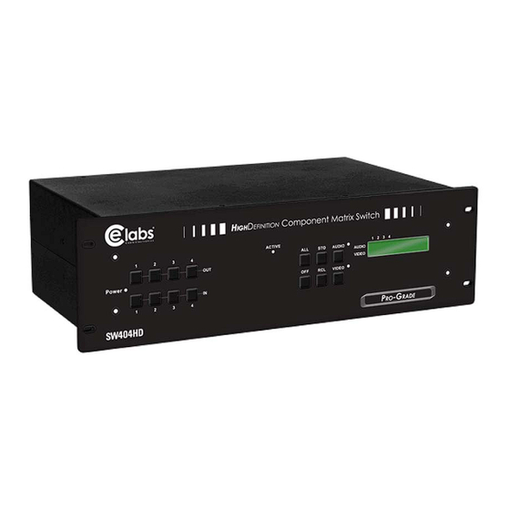
Page 6: Matrix System Front/Rear Panels
Page 2 Matrix Switching System—Instruction Manual Matrix System Front/Rear Panels Model SW404HD Front/Rear Panels SW404HD Front Panel SW404HD Rear Panel Model SW808HD Front/Rear Panels... -
Page 7: Matrix And Peripherals Connection
Matrix Switching System—Instruction Manual Page 3 SW808HD Front Panel SW808HD Rear Panel Matrix and Peripherals Connection Receiver Matrix System Connections... -
Page 8: Input/Output Jacks
Page 4 Input/Output Jacks Dependent on the matrix model installed, the video signal input/output jacks are arranged in either 4 or 8 columns of RCA female connectors. The connector rows from top to bottom are: Y video (green), Pb/Cb video (blue), Pr/Cr video (red), right audio signal (red), and left audio signal (white). -
Page 9: Connection Method
Use the RCA cables for connecting AV equipment to the matrix. Connect the video and audio connectors of the signal source equipment output terminals to the same channel connector of the matrix input terminals. Connect the output of the matrix switch to the input connectors of the interfaced equipment. -
Page 10: Rs-232 Communication Port Connection Methods
Page 6 RS-232 Communication Port Connection Methods The RS-232 port is a 9-pin female connector. The pin functions are shown in the following table and connections in the Illustrations below: Note: The Matrix RS-232 port is defined as DCE. Description number Send Receive... -
Page 11: Rs-485 Communication Port Connection Methods
RS-485 Communication Port Connection Methods The RS-485 port will control more than one product. The RS-485 Port is shown below. On/Off Switch Settings A. DIP switch 8:(RS-232/RS-485 on/off) ON:RS-232 enables single system or RS-485 serial master OFF:RS-485 enables RS-485 serial slave B. - Page 12 Page 8 Software ID ID Address Address (Decimal) (Hexadecimal ) Matrix Switching System—Instruction Manual ID Address Settings ON/OFF Switch Settings ON/OFF (Binary) 01001 01010 01011 01100 01101 01110 01111 10000 10001 10010 10011 10100 10101 10110 10111 11000 11001 11010...
-
Page 13: Matrix System And Control System Connection - Rs-232
TX (+) ↔ TX (+) TX (-) ↔ TX (-) RX (+) ↔ RX (+) RX (-) ↔ RX (-) 4. DIP switch 1-5 addresses must not set to same ID address. Page 9 (ID = 0) (ID = 1) -
Page 14: Matrix System And Control System Connection - Rs-485
(9600 – 8 - N - 1). 2. Connect PC RS-485 port to the Matrix RS-485 port 3. Serial connection between Matrix RS-485 ports 4. DIP switch 1-5 addresses must not set to same ID address. Matrix Switching System—Instruction Manual TX (+) ↔ TX (+) TX (-) ↔... -
Page 15: Matrix Control Panel Operation
Matrix Switching System—Instruction Manual Matrix Control Panel Operation Input/Output Switching Key Operation Mode The front panel keys of the Matrix system are used for fast audio/video switching (for details refer to the Front Panel Key Functions). Operation Operation consists of three basic steps: Choose the Switching Method Select the Output Channel Select the Input Channel. - Page 16 Page 12 Part Function Key (Store Key) (Retrieve Key) AUDIO VIDEO Matrix Switching System—Instruction Manual Front Panel Key Functions Implement all output selection keys via certain input route. Example: First press the ALL key, then select the input channel to output to all output channels;...
-
Page 17: Operation Examples
Matrix Switching System—Instruction Manual Operation Examples Example 1: Synchronously connect the number 1 audio/video input signals to the number 3 and 4 output channels (Audio and Video enabled). OUTPUT INPUT OUTPUT INPUT Example 2: Connect number4 video input signals from channel to number 1, 3, 5 and 6 output channels (Audio disabled and Video enabled). - Page 18 Page 14 OUTPUT INPUT OUTPUT INPUT OUTPUT INPUT Matrix Switching System—Instruction Manual Operation Example 2 LCD Display Operation 4. Press the OUT number 3 key (output channel). 5. When the Video LCD number under the 3 on the panel begins to flash press the IN number 4 shows channel number 3 for...
-
Page 19: Matrix Application Software
4. Insert the CD ROM provided and install AV Matrix.msi. 5. Click on the AV Matrix program under the start menu. 6. Click on the Scan button to connect to the matrix switch. Software Features The software controls signal connection between the corresponding input port and output port as required. -
Page 20: Examples For Selecting Matrix Switching Functions
Second method:. The following 3 steps sets the switching operation of Audio/Video input channel 1 to output channels 2, 3 and 5 while at the same time switch Audio/Video input channel 3 to output channel 6. Step 1: In the lower right corner of the blue area, enable the Video and Audio functions (check the white boxes), Matrix Switching System—Instruction Manual... - Page 21 1 to output channels number 1, 6 and 7 and also to switch from audio channel 2 to output channel 8. There are two ways of operations: First method: In the lower right corner of the blue area, enable the Video and disable the Audio functions (check/uncheck the white boxes).
-
Page 22: Disconnect Function Keys
Page 18 Matrix Switching System—Instruction Manual Disconnect Function Keys Close all the unused output ports. A specific example of operation is described below: The default input and output relations are shown below:... -
Page 23: Select All Output, Deselect All Output Switching Functions
Matrix Switching System—Instruction Manual Example: Close the output ports 03, 05, and 06. Step 1: First press down the output number keys 03, 05 and 06 to the right Step 2: Press the Disconnect key Step 3: Press the previously pressed output number keys 03, 05 and 06 (or press the Deselect all output key) to complete the operation. -
Page 24: Disconnect All Command Function Description
Page 20 Disconnect all: Command Function Description Use this command to close all the switching paths at one time. Press the Disconnect all key to close connection to all input and output ports. Memory Function Usage Store and Retrieve Function Description The Store Function saves all the present input/output switching relations to any Locations from #1 to #8 desired. -
Page 25: Exit Function Description
Matrix Switching System—Instruction Manual Exit Function Description Used to exit the operating software. Other Usages Displays the presently saved switching status as shown below: Communication Protocol and Control Command Code Communication Protocol: Baud rate 9600bps No, odd, or even parity 8-bit transmission address 1 bit stop address. -
Page 26: Video Output
9600bps, no odd or even parity, 8-bit Transmission Address , 1-bit Stop Address TX, RX, GND (AV Matrix)) 100VAC~240VAC, 50/60Hz, International Auto-Switch Storage, Operating Temp: -40°C~+85°C Storage, Operating Humidity: 10%~90% 485 mm (L) X 272 mm ( W ) X 140mm (H) -
Page 27: Common Problems And Solutions
Matrix Switching System—Instruction Manual Common Problems and Solutions 1. The matrix front panel switching keys not responsive? Answer: The matrix front panel keys employ scanning testing and require longer response time. Press the keys for 2 seconds and then release. This way, key switching will be responsive in operation. - Page 28 Page 24 10. The matrix panel keys and communication ports are out of order? Answer: Check if the equipment power input is good and the computer communication ports are good. If the connections are good, it could be failure of the product. Call 469-429 9200 for technical support.
-
Page 29: Appendix - Communication Protocol
APPENDIX – Matrix Switch Communication Protocol The RS-232/RS-485 communications are half-duplex with variable byte count packets. For RS-232, the matrix switch operates as a DCE device and therefore can be connected using a straight cable to a DTE device such as a computer. The RS-232 connector is a DB-9 female. -
Page 30: Protocol Description
Page 26 Protocol Description Command Packet Command packets are sent to the Matrix Switch from a computer and are 4 or more bytes long depending upon the instruction code. Command Type A Address Instruction Code or Command Type B Address... - Page 31 Matrix Switching System—Instruction Manual Address Byte (Command Type A and B) Broadcast Reserved BT: Broadcast 0: Instruction for one machine with matching Machine ID 1: Instruction for all machines If BT = 1, machine will not return a response packet. If BT = 0, machine must respond CRC: CRC-8 0: Host (computer) does not append a CRC byte at end of command...
-
Page 32: Response Packet Byte Descriptions
Page 28 Response Packet Byte Descriptions ACK Type A ACK Byte ACK Byte (ACK Type A, B, and C) Accept Reserved Reserved Machine ID (5-bit address) ACC: Accept: 0: Reject received command 1: Accept command ACK Type B Length Output Byte Byte Byte 1... -
Page 33: Command Table
SIP3 ASCII Code (character) Variable Output Byte Length Video output to Video input to switch 1 –8 switch 1 – 8 (0=all) (0= disconnect) Video output to Video input to be be switch 1 –8 switch 1 – 8 (0=all) - Page 34 Page 30 Instruction Instruction Description Code Request Status of Audio Output Request Machine Info and Model Command Note: 1. Not supported for Broadcast command. 2. Memory # 0 is current switching status, memory # 1-x is free location. Refer to Information Byte for number of total memory locations.
-
Page 35: Trademarks
Warranty Cable Electronics, Inc. warrants this product to be free from defects in material and workmanship, under normal use and service, for a period of one year from the purchase by the original purchaser. If this product is defective or malfunctions, Cable Electronics will replace or repair this unit (at their option) within a reasonable time.
Need help?
Do you have a question about the CE Labs SW404HD and is the answer not in the manual?
Questions and answers