
Related Manuals for HIOS BLG-7000BC2-GT-S


Summary of Contents for HIOS BLG-7000BC2-GT-S
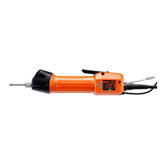
- Page 1 Built-in screwdriver & Pulse system BLG-BC2 Series BLG-4000BC2 / BLG-4000BC2-LT BLG-5000BC2 / BLG-5000BC2-15 / BLG-5000BC2-18 / BLG-5000BC2-HT BLG-7000BC2 / BLG-7000BC2-GT (-S/ -HANDLE) Operation Manual (2021.11) ET-A011-BC2-GT 21A...
-
Page 2: Table Of Contents
Table of Contents 03 Important Safety Instructions <Minimum Pulse> <Maximum Pulse> 05 Checking Supplied Accessories <Work Reset Timer> 06 Setting Up the Device <Count Timer for Reverse Rotation> Connecting the Cord <System> Installing with the Stand (BLG-7000BC2- <Pulse Detection> GT-S) <Total Torque-ups (count)>... -
Page 3: Important Safety Instructions
Important Safety Instructions Please read this manual and the power supply unit manual carefully before use to ensure proper operation. In addition, do not use the product in the way not described in this manual. Please note that we are not responsible for any problems caused by using the product in a manner that does not conform to the contents of this manual, using it improperly, or repairing / modifying by a third party except by us or someone specified by us. - Page 4 ◦ Do not give a strong impact or excessive force. ◦ We recommend genuine HIOS parts for Otherwise, it may cause a failure. replacement. ◦ Do not operate the screwdriver with wet or oiled hands.
-
Page 5: Checking Supplied Accessories
– (Ø5.0×50mm) Screwdriver cord: 2 m (6P) Hexagon L-shaped wrench: 5 mm across flats (BLG-5000BC2 Series/BLG-7000BC2 Only) Adjustment spring for low torque Instruction manual (BLG-4000BC2/BLG-4000BC2-LT Only) HANDLE (BLG-7000BC2-GT-HANDLE) Stand (BLG-7000BC2-GT-S) *Attached to the driver *Slide arm is attached to the driver... -
Page 6: Setting Up The Device
◦ The indicator on the power unit turns on. ▶ Installing with the Stand (BLG-7000BC2-GT-S) 1 Fix the stand, then put the shockless holder on the pole. ▶ 2 Adjust the position of the slide arm if needed. -
Page 7: Attaching A Bit
Attaching a Bit Caution Do not attach / remove the bit while power is on. Otherwise, it may cause an unexpected accident. 1 Insert the bit into the joint shaft collar. ◦ BLG-4000BC2 / BLG-4000BC2-LT: Attach the bit while pushing the joint shaft collar into the screwdriver. -
Page 8: Changing The Start Mode
Changing the Start Mode (for BLG-5000BC2 Series /BLG-7000BC2 Series) You can change the mode to push start for BLG-5000BC2 Series and BLG-7000BC2. In the push start mode, the screwdriver starts rotation when you press it into an object. BLG-5000BC2 Series 1 Remove the switch lever. -
Page 9: Blg-7000Bc2 Series
BLG-7000BC2 Series 1 Remove the switch lever. ◦ Remove the shaft screw. ◦ Be careful not to lose the lever spring. 2 Turn over the switch lever and attach it. 3 Re-attach the shaft screw. -
Page 10: Parts And Their Functions
Parts and Their Functions BLG-4000BC2 Series ❶ ❷ ❸ ❹ ❺❻ ❼ COUNT CONTROL Fail PASS ⓫ ❿ ❾ ❽ BLG-5000BC2 Series ❶ ❸ ❹ ❺❻ ❼ COUNT CONTROL Fail PASS ❿ ❾ ⓬ ❽ ❶ Joint shaft collar values of the screwdriver from an external device (e.g. -
Page 11: Blg-7000Bc2
BLG-7000BC2 ❶ ❸ ❺❻ ❼ COUNT CONTROL Fail PASS ❿ ❾ ❽ ❹ BLG-7000BC2-GT (-S/-HANDLE) ❶ ❸ ❺❻ ❼ COUNT CONTROL Fail PASS ❾ ❿ ❽ ❹ ❽ FOR/REV switch ⓫ Nut fixing ring (BLG-4000BC2-LT Only) You can change the rotational direction with This prevents the torque adjustment nut from this switch. -
Page 12: Operation Panel
Operation Panel ❶ F1 button This is used to change the mode to setting or ❶ ❷ ❸ change the setting items. ❷ F2 button This is used to change the mode to direct teaching or change the digit of the setting. ❸... -
Page 13: Basic Operations
Basic Operations 1 Set the FOR / REV switch to <FOR>. ◦ When you change the rotational direction, turn the switch to 0 to stop the screwdriver. 2 Start the screwdriver. ◦ In the lever mode, pull the switch lever for start. ◦... -
Page 14: Setting The Torque
Caution “Output Torque Guide” and the torque adjustment scale should be considered as a guide; they do not guarantee actual torques. Use the torque meter by HIOS to check the torque precisely. BLG-4000BC2 Series 1 Remove the protection cover of the torque adjustment nut. -
Page 15: Output Torque Guide (Hi Input)
Output Torque Guide (HI Input) N·m N·m Spring on the device 0.20 Spring on the device 0.15 Spring in the accessories 0.10 Spring in the accessories 0.05 0.03 2 3 4 5 6 7 8 2 3 4 5 6 7 8 Torque scale Torque scale How to Change to Smaller Torque... -
Page 16: Blg-5000Bc2 Series /Blg-7000Bc2
BLG-5000BC2 Series /BLG-7000BC2 1 Use the hexagon L-shaped wrench in the accessories to turn the torque adjustment nut for setting the fastening torque. ◦ Adjust the edge face of the torque adjustment nut to align with the scale. Output Torque Guide (HI Input) N·m N·m N·m... -
Page 17: Blg-7000Bc2-Gt
BLG-7000BC2-GT 1 Rotate torque adjusing nut to set torque. ◦ Adjust the edge face of the torque adjustment nut to align with the scale. Output Torque Guide (HI Input) N·m 3 4 5 6 7 Torque scale... -
Page 18: Setting The Pass / Fail Criteria
Setting the Pass / Fail Criteria This section describes how to set the pass / fail criteria. There are two ways of setting, direct teaching and manual setting. Setting by Direct Teaching Direct teaching uses real screws and workpieces. It measures the pulses of motor rotation from when the screwdriver starts turning to when it reaches the torque-up. - Page 19 2 Fasten a screw to a workpiece. ◦ The pulse is counted until the screw is seated. ◦ Repeat this teaching process at least three times. ▶ Fail PASS 3 Press and hold the F3 button to set the allowable range of the threshold.
-
Page 20: Setting By Manual Procedure
Setting by Manual Procedure Input the number of pulses directly to set the criteria. Caution If you set the criteria manually, the factor of allowable range has no effect. Then, you need to set the number of pulses considering the variances of screws and workpieces. 1 Press and hold the F1 button. -
Page 21: Setting Screw Counter
Setting Screw Counter Every time a screw is fastened correctly, the number of screws to be fastened on the display decreases (counting down). If the result is <Fail>, there is no counting down. 1 Press and hold the F1 button. ▶ ... - Page 22 When the Set Number of Screws Is Reached When counting down reaches the set number, the set number is displayed again. ▶ ▶ Fail PASS Fail PASS The buzzer starts when counting down reaches the set number. The time length of the buzzer can be specified via <Work Reset Timer>.
-
Page 23: Setting Menu List
Setting Menu List This device has various setup items and you can adjust each of them in detail. The setup value in bold is the default. How to Operate Setup Mode Press and Hold the F1 Button to Start Setup. Press and hold the F1 button to start setup. -
Page 24: Counter
<Counter> Here you can set whether to use all the functions including pulse counting, screw counter, etc. It sends out no data. Setup value On: all the functions are used OFF: the device is used as an ordinary screwdriver Fail PASS <Screw Counter>... -
Page 25: Work Reset Timer
<Work Reset Timer> Here you set the length of the buzzer when the number of screws set by <Screw Counter> is completed, and the reception time for cancellation of the final count down by reverse rotation. Setup value 0.0 to 1.0 to 3.9 seconds Fail PASS <Count Timer for Reverse Rotation>... -
Page 26: Pulse Detection
<Pulse Detection> This is used to set whether to detect an error of <Minimum Pulse> or <Maximum Pulse> in the judgment of pass / fail. If you select no detection, the result always becomes <PASS>. Setup value 0: No error is to be detected both for <Minimum Pulse> and <Maximum Pulse>. -
Page 27: Connecting The Special Cable (Option)
Connecting the Special Cable (Option) If you connect an optional special cable to this device, you can transmit / receive data to / from the peripheral devices including PCs, PLCs etc. Caution If <Counter> is set inactive, no data is sent. Confirm it is active before you start communication with external devices. -
Page 28: Connecting To Screwdriver
Connecting to Screwdriver (BLG-4000BC2/BLG-5000BC2 Series) 1 If necessary, remove the screwdriver cord from the screwdriver. ◦ Turn off the power before removing the cord. 2 Tilt the hanger. 3 Connect the special cable to the I/O port. 4 Attach the clasp for holding to the connector. ◦... - Page 29 5 Connect the screwdriver cord. ◦ Use the joint ring to fix the cord. 6 Use the cable tie to fix the special cable and the screwdriver cord. ◦ Fix the special cable so that it does not move. ◦ Fix it at a few points along the screwdriver cord. Caution A Loop to Avoid Excessive Load A loop of the cable is made by a cable tie so that it has some...
-
Page 30: Connecting To Screwdriver (Blg-7000Bc2)
Connecting to Screwdriver (BLG-7000BC2) 1 How to connect to screwdriver 2 Connect the special cable to the I/O port. 3 Use the cable tie to fix the special cable and the screwdriver cord. ◦ Fix the special cable so that it does not move. ◦... -
Page 31: Saving Screw Fastening Data
Saving Screw Fastening Data The CD-ROM supplied with the special cable contains a tool for saving screw fastening data obtained when using this device. The data is saved in CSV format. By using the tool you can also save the setting data on a PC, check operations or send / receive communication commands. If the CD-ROM is not included, please download it from our website. -
Page 32: Connecting To Screwdriver
Connecting to Screwdriver 1 Activate [Counter_BC2_Ch4_Normal_Ver2.05.exe]. 2 Select [Save_Folder] in the [Folder] menu to decide where to save the data. ◦ The file path is displayed. ◦ The data are saved for each date. 3 In the pull-down menu, select the port number to which the screwdriver is connected. -
Page 33: Sending Command
How to Read Output Data You can review the operational status of the screwdriver and the pass / fail result in the log displayed in the log window on a real time basis. For details of the messages and commands, refer to “Communication Command / List of Messages”... - Page 34 ❶ Allowable range (Rate (R)) This specifies the allowable range to the pass / fail criteria. ❷ <Counter> You can set whether to use all of the functions including pulse counting, screw counter, etc. If [Off ] is set, no data is sent. ❸...
-
Page 35: Work Monitor
⓮ Unlock button The screwdriver will be locked, and the button will be on when the total torque-ups reaches 1 million. It is unlocked with a click. Work Monitor You can review the operational status of the screwdriver on a real time basis. ❶... -
Page 36: Screen Of Administration
Screen of Administration Select this screen in the menu of [Setting] of Connection screen to control set values of the screwdriver from the PC. For each screw fastening term, you send a file after reading it or save the changes. ❶... - Page 37 How to send from setting file 1 Read the setting file by selecting [Open] in the [File] menu if necessary. 2 Click the channel to send the file. ◦ All the setting values in the channel are selected. 3 Select the COM port in the list to which you want to send the change, and click the [Set] button.
-
Page 38: Specifications Of Communication By Special
Specifications of Communication by Special Cable ◦ Pin numbers 3: RXD 5: COM 2: TXD Data transmission speed: 38,400 bps ◦ ◦ Data bit: 8 bits Stop bit: 1 bit ◦ ◦ Parity: none Communication format: ASCII ◦ Message Format The message format has two types: setting command and inquiry command. -
Page 39: Communication Command / List Of Messages
Communication Command / List of Messages When communication with the screwdriver is established, the following settings saved in the screwdriver will be sent. AR, AP, An, Ac, AC, At, Ar, Ad, AU, Ao, AG Command to Setting Message from confirm the Function change Details... - Page 40 Command to Setting Message from confirm the Function change Details set value of screwdriver command screwdriver To set whether to use the buzzer sound and reverse counting. x=0 to 3 0: Buzzer: active / reverse counting: active 1: Buzzer: active / reverse counting: inactive System Sd:xy...
- Page 41 Command to Setting Message from confirm the Function change Details set value of screwdriver command screwdriver To set whether or not to enable the Switch lever switch lever operation. Lv:x Lv:x - operation 0: Enable 1: Disable (OFF is on the display) Detection of 0: Disable (OFF is on the display) -...
- Page 42 Command to Setting Message from confirm the Function change Details set value of screwdriver command screwdriver This is sent when reverse operation is done if the reverse counting is active. Message of reverse R:x,Number x=the number of screws to be -...
-
Page 43: Troubleshooting
Also refer to “Attaching a Bit” (P. 07) to see if you attached it correctly. The torque is too small to Check if you used a genuine HIOS product and if you used the ◦ fasten a screw sufficiently. specified torque adjustment spring. -
Page 44: When The Messages Below Are Displayed
When the Messages Below Are Displayed When the total fastening exceeds one million, this message ◦ will be displayed, and the screwdriver will be locked. In that case, overhaul or maintenance is required. Please contact your dealer or our service department. Fail PASS If you want to unlock it temporarily, press and hold the F2... -
Page 45: Maintenance
Maintenance We determined the guarantee period by assuming the screwdriver is used 8 hours a day. We recommend periodic overhaul inspection once a year. After sales services. About BLG-7000BC2-GT Check that tarret and handle are firmly fastened on a regular basis. If it is loose, fasten it with specified torque again. -
Page 46: Specifications
Specifications The device specifications are subject to change without prior notice due to improvements of the device. BLG-4000BC2 Series Unit [mm] 206 (BLG-4000BC2) 207 (BLG-4000BC2-LT) COUNT CONTROL 46.0 32.7 Fail PASS Model BLG-4000BC2 BLG-4000BC2-LT Output Torque Range (N ・ m) 0.1 to 0.55 0.03 to 0.2 Unloaded... - Page 47 BLG-5000BC2 Series Unit [mm] 214.0 31.0 COUNT CONTROL 46.0 38.0 Fail PASS Model BLG-5000BC2 BLG-5000BC2-15 BLG-5000BC2-18 BLG-5000BC2-HT Output Torque Range (N ・ m) 0.2 to 1.2 0.3 to 1.0 0.5 to 1.5 0.5 to 2.0 Unloaded 1,000 1,500 1,800 Rotation Speed 1,000 1,200 –...
-
Page 48: Blg-7000Bc2
BLG-7000BC2 Unit [mm] 37.0 COUNT CONTROL 40.0 Fail PASS Model BLG-7000BC2 Output Torque Range (N ・ m) 0.7 to 2.8 1,200 Unloaded Rotation Speed (r.p.m) ±10% Machine Screw 2.6 to 5.0 Screw Size (mm) Tapping Screw 2.6 to 4.0 Standard H5 and 5HEX Bit Drive Option... -
Page 49: Blg-7000Bc2-Gt
71.5 COUNT CONTROL 41.8 57.0 18.4 Fail PASS 242.7 48.2 46.6 BLG-7000BC2-GT-HANDLE BLG-7000BC2-GT-S Model BLG-7000BC2-GT-HANDLE Output Torque Range (N ・ m) 2.0 to 5.0 Unloaded Rotation Speed (r.p.m) ±10% Machine Screw 4.0 to 6.0 Screw Size (mm) Tapping Screw 4.0 to 6.0... - Page 50 Unit [mm] BLG-7000BC2-GT-S 62.55 Ø44 COUNT CONTROL 41.8 18.4 Fail PASS 242.7 Model Shockless Stand Slide arm 530 mm (effective sliding range in (475 mm) parenthesis) Height of pole 570 mm Height of base 8 mm Attachment bolts inner diameter of...
-
Page 51: Notice
Notice Disclaimer The information in this document is subject to change without notice. Trademarks Microsoft, and Windows are either registered trademarks or trademarks of Microsoft Corporation in the United States and/or other countries. All other product and brand names are registered trademarks, trademarks or service marks of their respective owners. - Page 52 HIOS Inc. 1-35-1 Oshiage, Sumida-ku Tokyo, Japan 131-0045 www.hios.com...
Need help?
Do you have a question about the BLG-7000BC2-GT-S and is the answer not in the manual?
Questions and answers