Table of Contents
Advertisement
Advertisement
Table of Contents

Related Manuals for Auto Crane 4004EH


Summary of Contents for Auto Crane 4004EH
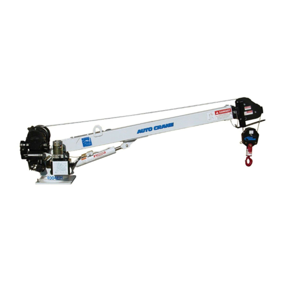
- Page 1 4004EH OWNERS MANUAL Manual No. 999980000 Rev. 04/14/06 Serial No. __________________ Mailing Address: P.O. Box 580697 Tulsa, OK 74158-0697 Physical Address: Phone (918) 836-0463 4707 N. Mingo Rd. Fax (918) 834-5979 Tulsa, OK 74117-5904 http://www.autocrane.com...
- Page 3 Serial No.: Date Product Delivered: Date Processed:* VIN # * For Auto Crane use only ONE REGISTRATION FORM PER UNIT (CRANE OR BODY) Registration form must be mailed or faxed within 15 days of customer installation. Mail to: Warranty Department Auto Crane Company P.O.
- Page 5 1. The information contained in this manual is in effect at the time of this printing. It does not cover all instructions, configurations, accessories, etc. If you require additional information, please contact Auto Crane Company at (918) 836-0463. 2. Auto Crane Company reserves the right to update this material without notice or obligation.
- Page 7 ♦ Attempt to lift or drag a load from the side! The boom can fail far below its rated capacity. ♦ Weld, modify, or use unauthorized components on any Auto Crane unit! This will void any warranty or liability. Also failure of the crane may result.
-
Page 9: Table Of Contents
4004EH TABLE OF CONTENTS INTRODUCTION 1-1.0 GENERAL SPECIFICATIONS 1-3.0 SAFETY TIPS AND PRECAUTIONS 2-1.0 OPERATING PRACTICES & WARNINGS 2-3.0 QUALIFICATIONS FOR OPERATORS 2-4.0 OPERATION OF UNIT / OUTRIGGERS 2-7.0 INSPECTION 3-1.0 TESTING 3-4.0 MAINTENANCE 3-5.0 BATTERIES 3-7.0 LUBRICATION AND MAINTENANCE SCHEDULE 3-9.0... -
Page 11: Introduction
The payload of the vehicle is reduced by the If, through no fault of Auto Crane Company, it weight of the crane. The operator should is necessary to send an experienced factory exercise care when loading the vehicle. - Page 12 Auto Crane Company at the following telephone number: (918) 836-0463. The information contained in the manual is in effect at the time of this printing. Auto Crane Company reserves the right to update this material without notice or obligation. 1-2.0...
-
Page 13: General Specifications
4004EH GENERAL SPECIFICATIONS DIMENSIONS REACH Width: 22 in (0.56 m) Second boom will reach from 8 feet to 12 feet Third boom will reach from 12 feet to 16 feet Height: 27.00 in (0.69 m) Length: 9 ft 10 1/2 in (3.30 m) -
Page 14: Safety Tips And Precautions
30. Always store outriggers before transportation. WARNING! Auto Crane Company cranes are not designed or intended for use in lifting or moving persons. Any such use shall be considered to be improper and the seller shall not be responsible for any claims arising there from. - Page 15 --- IMPORTANT --- SAFETY TIPS AND PRECAUTIONS 31. Always store the crane in its stowed position 41. Do not push down on anything with boom for transportation. extensions; similarly do not lift anything with boom extensions. 32. Remember the overall height of the entire unit for garage door clearance or when 42.
-
Page 16: Operating Practices & Warnings
NEVER hold any Control Select Switch on that will cause unsafe operating conditions! WARNING! Auto Crane Company remote controlled, stiff boom cranes are not designed or intended for use on any applications involving the lifting or moving of personnel. 2-3.0... -
Page 17: Qualifications For Operators
QUALIFICATIONS FOR AND CONDUCT OF OPERATORS AND OPERATING PRACTICES REFERENCE ASME B30.5a AND OSHA 1910.180 FOR COMPLETE QUALIFICATION REQUIREMENTS tests may be required to determine these OPERATORS conditions. 1. Crane operation shall be limited to personnel 5. Operators and operator trainees should have with the following minimum qualifications: normal depth perception, coordination, and no tendencies to dizziness or similar undesirable... - Page 18 QUALIFICATIONS FOR AND CONDUCT OF OPERATORS AND OPERATING PRACTICES or neutral position and all personnel are in the C. Means are provided to hold the vehicle clear. stationary while operating the crane. 6. If power fails during operation, the operator shall: D.
- Page 19 QUALIFICATIONS FOR AND CONDUCT OF OPERATORS AND OPERATING PRACTICES N. No person should be permitted to stand or 3. Caution shall be exercised when working near pass under a suspended load. overhead lines, because they can move horizontally or vertically due to wind, moving the 4.
-
Page 20: Operation Of Unit / Outriggers
--- IMPORTANT --- OPERATION OF UNIT 1. Make sure this manual has been thoroughly 8. Always boom up before rotating so the boom will read by all crane operating personnel and clear the required boom support. supervisors. 9. When extending the boom, always maintain 2. -
Page 21: Inspection
INSPECTION REQUIREMENTS REFERENCE ASME B30.5a AND OSHA 1910.180 FOR COMPLETE INSPECTION REQUIREMENTS INSPECTION CLASSIFICATION 3. Inspect safety devices for malfunction. 4. Visually inspect all hydraulic hoses, particularly 1. Initial inspection. those that flex in normal operation of crane functions. Prior to initial use, all new, altered, modified or extensively repaired cranes shall be inspected by a 5. - Page 22 INSPECTION REQUIREMENTS PERIODIC INSPECTION B. Improper return of spool to neutral position. C. Leaks at spools or joints. Any deficiencies, such as those listed below, shall be D. Sticking spools. carefully examined and determination made as to E. Failure of relief valves to attain or maintain whether they constitute a hazard: correct pressure setting.
- Page 23 INSPECTION REQUIREMENTS A. Reduction of rope diameter below nominal diameter due to loss of core support. B. Internal or external corrosion. C. Wear of outside wires. D. Severely corroded, cracked, bent, worn, or improperly applied connections. CRANES NOT IN REGULAR USE A crane, which has been idle for a period of over one month or more, shall be given an inspection conforming to the “initial”...
-
Page 24: Testing
TESTING REQUIREMENTS REFERENCE ASME B30.5a AND OSHA 1910.180 FOR COMPLETE TESTING REQUIREMENTS TESTING SHALL BE PERFORMED BY DESIGNATED PERSONNEL ONLY. Prior to initial use, all new, altered, modified, or extensively repaired cranes shall be tested for compliance with the operational requirements of this crane. Test requirements: 1. - Page 25 GENERAL REPAIRS AND MAINTENANCE REFERENCE ASME B30.5a AND OSHA 1910.180 FOR COMPLETE MAINTENANCE AND REPAIR REQUIREMENTS A preventative maintenance program should be B. Critical parts of the crane structure which are established based on this section and all replacement cracked, bent, broken, or excessively corroded. parts should be obtained from AutoCrane Company.
- Page 26 GENERAL REPAIRS AND MAINTENANCE (2.4 mm) for diameters 11/4 in. (32 mm) to and side of the cut are required, and for non-preformed including 11/2 in. (38 mm). rope 1 in. (25 mm) diameter or larger, three seizings on each side of the cut are required. G.
-
Page 27: Maintenance
MAINTENANCE OF BATTERIES Maintenance of Auto Crane unit batteries differs deterioration of the remaining parts of the very little from the generally prescribed battery. maintenance of any lead acid battery. All batteries Keep A Relatively Clean Battery must be kept properly charged, properly filled with water, and relatively clean. - Page 28 MAINTENANCE OF BATTERIES If, after charging, it is noted that the specific gravity 2. Place the battery on charge according to the reading of one cell is 30 points less than any of the manufacturer's instructions. other cells, it may be assumed that the cell is bad and that the battery should be replaced.
- Page 29 4004EH LUBRICATION & MAINTENANCE SCHEDULE SERVICE NOTES DAY WKLY 3 MOS 6 MOS YEAR PERFORMED INSPECT HOOK & LATCH FOR DEFORMATION, LOAD HOOK CRACKS, & CORROSION MAKE SURE CABLE IS WOUND EVENLY ON CABLE DRUM DRUM HOIST / BOOM CHECK FOR FLATTENING, KINKS, & BROKEN...
-
Page 30: Lubrication And Maintenance Schedule
2. Once a bolt has been torqued to its rated capacity and then removed; the bolt should be replaced with a new one. 3. Auto Crane Company recommends that this crane be serviced per “Crane Inspection Log” P/N 999978. These logs should be filled in at the intervals noted and kept as a permanent record. -
Page 31: Safety Decal Section
4004EH SAFETY DECAL SECTION PART NO.: 040579000 DECAL: OPERATING INSTRUCTIONS FUNCTION: To inform the operator of the proper procedure to follow for safe operation of the crane. USED ON: All Cranes. QUANTITY: PLACEMENT: Right side plate. PART NO.: 040580000 DECAL:... - Page 32 4004EH SAFETY DECAL SECTION PART NO.: 040529000 DECAL: ELECTROCUTION HAZARD FUNCTION: To inform the operator of the hazard involved with contacting electrical power lines with crane boom. USED ON: All Cranes. QUANTITY: PLACEMENT: Both sides of end of lower boom.
- Page 33 4004EH SAFETY DECAL SECTION PART NO.: 040587000 USED ON: All cranes equipped with a load sensor. DECAL: LOAD SENSOR, DON'T TAMPER QUANTITY: FUNCTION: To inform the operator that the load PLACEMENT: Both sides of the lift cylinder near sensor is pre-set and that tampering the load sensor.
- Page 34 NOTES...
- Page 35 4004EH SAFETY DECAL SECTION PART NO.: 460169000 USED ON: All Cranes equiped with FM controls. DECAL: REMOTE CONTROL QUANTITY: FUNCTION: To inform the operator of failure to PLACEMENT: FRONT OF POWER UNIT follow the saftey precautions may result in equipment failure or serious personal injury.
- Page 36 4004EH DECAL LAYOUT P/N: 404209000 FM UNITS ONLY, MOUNTED IN FRONT OF RESERVOIR 4-5.0 3/20/06...
- Page 37 DECAL ANGLE INDICATOR SS 330622000 DECAL SERIAL NO 360034000 DECAL AUTO CRANE LOGO 460169000 DECAL WARNING, REMOTE CONTROL 404207000 DECAL 4004EH LOAD CHART 404225000 DECAL, RECEIVER/PENDANT 404208000 DECAL 4004EH, HORIZONTAL 404212000 DECAL MAX BLOCK LOAD 4004 600047000 DECAL AUTO CRANE 4-6.0...
-
Page 38: General Dimensions
4004EH GENERAL DIMENSIONS 9 5/8" 13/16" HOLE (USE 3/4-16UNF GR8 MOUNTING BOLTS) 9" MIN HOLE INSTALLATION REQUIRED 14 3/4" 16 3/4" 15'-10 1/4" 1" 11 1/2" 1" 13 1/2" 13 1/4" 12 1/4" 7'-10 3/4" 9 9/16" R17.67 23 5/8"... -
Page 39: Mounting And Installation
9. Load test the crane to ensure proper functioning and truck stability 10. Make certain the owner’s manual is delivered to the customer. 11. For additional help: call the service department at the Auto Crane Company. (918) 836-0463 (Tulsa, Oklahoma) - Page 40 4004EH GENERAL ASSEMBLY HARDWIRED – P/N: 404181000 APPLY LOCTITE 242 TO THREADS BEFORE INSTALLATION 4 6 12 2 6 9 11 APPLY LOCTITE 242 TO THREADS BEFORE INSTALLATION EXTEND RETRACT PORT B1 PORT A1 6-1.0 04/14/06...
- Page 41 4004EH GENERAL ASSEMBLY HARDWIRED – P/N: 404181000 DESCRIPTION ITEM NO. QTY. PART NO. 404190000 PEDESTAL ASSY, 4004EH 404220000 PIN WDMT B00M/PED 404189000 BOOM ASSY 4004 320824000 PIN, LIFT CYLINDER 404211000 TRAVELING BLOCK ASSY, 4004 021200000 WASHER FL 3/8 239000000 ZERK DRIVE GR...
- Page 42 4004EH PEDESTAL ASSEMBLY P/N: 404190000 32 23 31 30 29 55 56 4 55 56 22 21 HYDRAULICS: PORT B-1 RETRACT PORT B-2 BOOM UP PORT B-3 CCW REAR MOTOR PORT A-1 EXTEND PORT A-2 BOOM DOWN PORT A-3 CC FRONT MOTOR CYLINDER SEAL KIT: 366342001 C’BAL CARTRIDGE: 480188000...
- Page 43 4004EH PEDESTAL ASSEMBLY P/N: 404190000 60 61 46 42 40 24 19 6-4.0 04/14/06...
- Page 44 UPPER VALVE BRACKET, 4004 404195000 UPPER TWECO BRACKET WLDMT, 4004 404201000 COVER, VALVE, 4004 320824000 PIN, LIFT CYLINDER 404197000 RELAY PANEL ASSY, 4004EH 020200000 WASHER SP LK 1/4 005500000 SCREW HX HD 1/4-20UNC X 3/4 LG 021100000 WASHER SP LK 3/8 330371000...
- Page 45 4004EH PEDESTAL ASSEMBLY P/N: 404190000 DESCRIPTION ITEM NO. QTY. PART NO. 812026016 HOSE ASSY -4 HOSE -6 FEMALE JIC 812026018 HOSE ASSY 812026031 HOSE ASSY -4 HOSE -6 FEMALE JIC 200876000 FITTING 6 SAE/6 JIC STRAIGHT 490198000 FITTING 10SAE(M)/6JIC ELBOW 90...
- Page 46 4004EH BOOM ASSEMBLY P/N: 404189000 30 29 22,23,24 NOTES: APPLY LOCTITE 242 TO BOLT THREADS, 12 PLCS BEFORE INSTALLING. CYLINDER SEAL KIT: 404169100 C’BAL CARTRIDGE: 480188000 6-7.0 04/14/06...
- Page 47 4004EH BOOM ASSEMBLY P/N: 404189000 PART NO. DESCRIPTION ITEM NO. QTY. 404184000 LOWER BOOM WELDMENT 404185000 MID BOOM WLDMNT 4004 366184000 RETAINER EXTENSION CYLINDER 404196000 CYLINDER, 2.50 X 1.75 X 48.01 404186000 UPPER BOOM WLDMT 4004 480130000 SHEAVE ASSY 360823000 2-BLOCK WDMT 5005EH...
- Page 48 NOTES...
- Page 49 4004EH HOIST ASSEMBLY P/N: 113003 ITEM NO. QTY. PART NO. DESCRIPTION 366656000 HOIST FRAME 297036 GEAR HSG/SPUR GEAR HSG/MTR 366660000 DRUM WELDMENT 330468 COLLAR, SPLIT 1.25 I.D. 320887000 BEARING, BRONZE 400500 BEARING 1.25 I.D. 366659000 TIE BAR, HOIST ASSEMBLY 021100...
- Page 50 4004EH HOIST ACTUATOR P/N: 297036 6-10.0 2/15/06...
- Page 51 4004EH HOIST ACTUATOR P/N: 297036 ITEM NO. QTY. PART NO. DESCRIPTION 306034 SPRING FLAT 314008 PLATE CAM 324106 COVER SPUR GEAR HOUSING 328128 COVER BRAKE 328134 COVER WORM GEAR HOUSING 334001 IDLER GEAR 334003 SPUR GEAR 334129 PINION GEAR 334165...
- Page 52 4004EH HOIST ACTUATOR P/N: 297036 ITEM NO. QTY. PART NO. DESCRIPTION 450001 KEY WOODRUFF 450016 KEY BARTH 456008 RELIEF FITTING 458108 MOTOR 12V 462015 O-RING 468002 REDUCER 468011 PIPE PLUG SQ HD 468017 PIPE PLUG SOC HD 468018 PIPE PLUG SOC HD...
- Page 53 4004EH TRAVELING BLOCK ASSEMBLY P/N: 404211000 ITEM NO. QTY. PART NO. DESCRIPTION 480362000 SHORT BLOCK SIDE PL WDMT 480130000 SHEAVE ASSY 480364000 TACKLE LOWER 480372000 BOLT, SHEAVE W/ ZERK FITTING 480367000 PIN BLOCK 480371000 HOOK SWIVEL 3 METRIC TON 480368000...
- Page 54 4004EH RELAY PANEL ASSEMBLY P/N: 404197000 G N D HT U P HT D N BO O TS REQ UIRED REF FO R REPLACEMENT PART O NLY N O TE (68 0 17 10 0 0 RECEPTACLE/W IRE PIG TAIL) * N O T SHO W N ITEM NO.
- Page 55 4004EH ELECTRICAL SCHEMATIC P/N: 404197000 +12V PUMP MOTOR PUMP RELAY PUMP (WHT/BLK) BOOM DOWN (BLU) BOOM DOWN RETRACT (ORG/BLK) RETRACT BOOM UP (BLU/BLK) BOOM UP HOIST UP (GRN) HOIST UP RELAY +12V HOIST MOTOR ROT CW (ORG) ROT CW + (RED)
- Page 56 40004EH PENDANT 8 FUNCTION W/ ON/OFF SWITCH - P/N: 366709001 PENDANT HEAD CW (ORG) CCW (WHT/RED) EXTEND (GRN/BLK) RETRACT (ORG/BLK) PUMP (WHT/BLK) BOOM UP (WHT) BOOM DN (BLU) HOIST UP (GRN) HOIST DN (RED/BLK) VOLTAGE SWITCHING UNIT (WHT/RED) + (RED) POWER CANNON PLUG...
- Page 57 40004EH PENDANT 8 FUNCTION W/ ON/OFF SWITCH - P/N: 366709001 ITEM NO. QTY. PART NO. DESCRIPTION 480501000 PENDANT HOUSING 366719000 DECAL, PENDANT 8 FUNC W/PWR 480504000 PENDANT BACK PLATE 370433000 CORD CONNECTOR HUBBLE F-3 680172000 PENDANT CABLE, 19 PIN BAYONET 480598000 COVER TRIGGER OPENING 750090000...
- Page 58 NOTES...
- Page 59 4004EH TWECO W/SWITCH MOUNT P/N: 404218000 ITEM NO. QTY. PART NO. DESCRIPTION 404217000 LOWER TWICO WLDMNT W/ SWITCH MNT 404224000 CABLE ASSY 11 IN, TWECO TO TERMINAL 002900000 SCREW SET .25-20UNC X .25 LG 404216000 MASTER SWITCH 404219000 DECAL, CRANE POWER 7-4.0...
- Page 60 4004EH HYDRAULIC CONTROL VALVE P/N: 320826000 INSIDE PORT ON POWER UNIT (PRESSURE) EXTEND PORT RETRACT PORT (EXT) (RET) EXTEND COIL RETRACT COIL BOOM DOWN COL BOOM UP COIL ROTATE CCW ROTATE CW COIL COIL B OOM DOWN BOOM UP PORT (RET)
- Page 61 4004EH POWER UNIT P/N: 320825000 ITEM NO. QTY. PART NO. DESCRIPTION 320825001 RESERVOIR KIT 200545000 BREATHER CAP 320825002 RELIEF VALVE KIT 320335005 MOTOR 320336005 RETURN PORT PLUG KIT 320825003 ADAPTER KIT 320335003 PUMP KIT 320335010 O-RING 8-2.0 02/15/06...
- Page 62 4004EH GENERAL ASSEMBLY FM – P/N: 404180000 APPLY LOCTITE 242 TO THREADS BEFORE INSTALLATION 6 8 18 3 8 11 4 13 15 NOTE: APPLY LOCTITE 242 ITEMS 13,14 & 15 USE TO THREADS BEFORE TO MOUNT TWECO INSTALLATION EXTEND...
- Page 63 4004EH GENERAL ASSEMBLY FM – P/N: 404180000 DESCRIPTION ITEM NO. QTY. PART NO. 404190000 PEDESTAL ASSY, 4004EH 404220000 PIN WDMT B00M/PED 404189000 BOOM ASSY 4004 320824000 PIN, LIFT CYLINDER 404211000 TRAVELING BLOCK ASSY, 4004 021200000 WASHER FL 3/8 239000000 ZERK DRIVE GR...
- Page 64 FM CONTROL USE AND CARE TRANSMITTER LAYOUT There is a red light to the left of the ON/OFF Toggle switch and a yellow light to the right. As the battery runs down, the red light will begin to flash as well as the yellow light. If the yellow light is rapidly flashing this indicates that the unit is transmitting.
- Page 65 FM CONTROL TRANSMITTER - P/N: 460157000 ITEM NO. QTY. PART NO. DESCRIPTION 460166000 TOGGLE SWITCH KIT (OMNEX) 460168000 HANDLE, TRANSMITTER W/O TRIGGER 460163000 COVER, TRANSMITTER BATTERY W/MAGNET 460162000 GUARD, TRIGGER (OMNEX) TOGGLE SWITCH WIRING CHART FUNCTION WIRE COLOR TERMINAL POSITION POWER ON YELLOW BOTTOM...
- Page 66 NOTES...
- Page 67 4004EH ELECTRICAL SCHEMATIC FM – P/N: 404206000 ELECTRICAL SCHEMATIC FM (WHT/BLK) (BLK) A (GREY PLUG) PUMP GROUND POWER W/LINK (RED) POWER EXTEND (GRN/BLK) RETRACT (RED) (ORG) (WHT/RED) (GRN) B (BLACK PLUG) (RED/BLK) ROTATE CW ROTATE CCW (WHT) WINCH UP WINCH DOWN...
- Page 68 FM CONTROL TRANSMITTER DIAGNOSTICS YELLOW YELLOW Tether connection detected YELLOW Low battery. Unit will run approximately 10 hours after Battery light starts flashing. Flashing rapidly for 10 seconds indicates a transmitter failure. Normal Operation YELLOW The Active light will flash several times per second, indicating that the transmitter is sending signals to the receiver.
- Page 69 FM CONTROL RECEIVER DIAGNOSTICS Normal Operation ESTOP FAULT LINK STATUS Transmitter is OFF If the transmitter is off, the receiver is operating properly. Transmitter is ON When the transmitter is turned on, the Link light (fast flashing) and E-Stop (GREEN) indicates the receiver is operating properly Transmitter is in Operation When a function is activated on the transmitter, the Fault light will turn on GREEN.
- Page 70 FM CONTROL TROUBLESHOOTING CHART 1 Test the Receiver—R160 OK state: Start Status—GREEN Initial Condition: Link—RED What is the state Turn transmitter off (all lights are off—press Fault—OFF of the lights on [POWER] OFF) E-Stop—RED the receiver? Cycle power to receiver (turn off and back on) Note: If there is a short to ground on an output, it is not indicated at this stage.
- Page 71 FM CONTROL TROUBLESHOOTING CHART 2 Test the Transmitter—T150 Turn off the receiver Ensure there are good batteries in the transmitter Turn on the transmitter OK state: Active light—steady for Activate a What is the state of about 3 seconds then function the lights? goes to fast flash.
- Page 72 FM CONTROL TROUBLESHOOTING CHART 3 Testing the Transmitter / Receiver Communication Transmitter: Transmitter: Active light is flashing Active light is flashing Receiver: What is the status of Receiver: Status—GREEN the lights of both the Status—GREEN Link—RED transmitter and Link—Flashing GREEN Fault—OFF receiver? Fault—OFF...
- Page 73 FM CONTROL ID CODE PROGRAMMING Download ID Code (Use in case of Link Test failure) !!Caution!! Note: Before attempting reprogramming with another transmitter, understand that re- programming the receiver with another transmitter, could result in two receivers on the job site responding to the one transmitter. If the original transmitter was sent in for repair, disconnect the receiver (disconnect connector A) to continue using the machine without remote capability and without fear of inadvertently operating the machine with Connector A...
- Page 74 FM CONTROL ID CODE PROGRAMMING (CONT.) 3. Power Transmitter into Configuration Mode A. Press & hold [BOOM] switch in the UP position YELLOW YELLOW YELLOW B. Press & release [POWER] switch in the OFF position C. Release [BOOM] switch The ACTIVE LED will flash once per second. 4.
- Page 75 4004EH LOAD CHART P/N: 404207000 13-1.0 02/15/06...
- Page 76 NOTES...
- Page 77 2 YEAR PARTS AND LABOR Auto Crane will warranty to the consumer for a period of (2) years parts and labor from the date of purchase. Each new Auto Crane unit they sell will be free under normal use and service from defects in material and workmanship.
Need help?
Do you have a question about the 4004EH and is the answer not in the manual?
Questions and answers