Table of Contents
Advertisement
Quick Links
Advertisement
Table of Contents

Subscribe to Our Youtube Channel
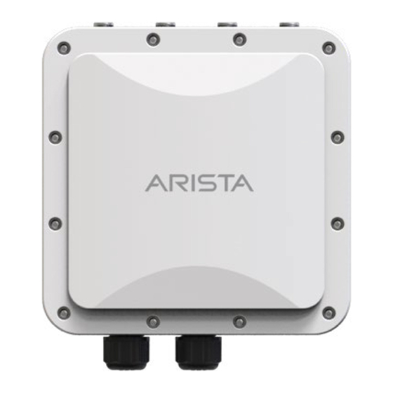
Summary of Contents for Arista O-105E
- Page 1 Quick Start Guide O-105E Access Point Arista Networks www.arista.com DOC-03652-02...
- Page 2 © Copyright 2020 Arista Networks, Inc. The information contained herein is subject to change without notice. Arista Networks and the Arista logo are trademarks of Arista Networks, Inc in the United States and other countries. Other product or service names may be trademarks or service marks of others.
-
Page 3: Table Of Contents
Wall Mount the O-105E......................10 Connect External Antennas to O-105E..................13 Power On the O-105E........................13 Connect the O-105E to the Network................... 14 Connect the O-105E using PoE...................14 Chapter 5. Access Point Troubleshooting..................15 Chapter 6. Appendix A: AP-Server Mutual Authentication............16... -
Page 4: Chapter 1. About This Guide
EULA from https://www.arista.com/en/support/product-documentation. Installation constitutes your acceptance of the terms and conditions of the EULA. Intended Audience This guide can be referred to by anyone who wants to install and configure the O-105E outdoor access point. Document Overview This guide contains the following chapters: •... -
Page 5: Chapter 2. Package Content
The access point (AP) package must contain the components shown in the following figure. Figure 1. Package Components Table 1. Labels: Package Components Label Description O-105E Access Point Mounting Bracket 4 screws for fixing bracket on the wall 4 screws for fixing bracket on the wall 2 black sealing pins... - Page 6 Important: The MAC address of the device is printed on a label at the bottom of the product and the packaging box. Note down the MAC address, before mounting the device. If the package is not complete, please contact Arista Networks Technical Support Team at support- wifi@arista.com...
-
Page 7: Chapter 3. Access Point Overview
• Side Panel of O-105E (on page 4) • Bottom Panel of O-105E (on page 5) Side Panel of O-105E The side panel of the O-105E has LEDs that indicate the working of the device. Figure 2. O-105E Side Panel... -
Page 8: Bottom Panel Of O-105E
Bottom Panel of O-105E The bottom panel of the O-105E has LAN or PoE connectors that enable you to connect the device to a wired LAN through a switch or a hub. The ports provide power for the device by using the 802.3at standard. - Page 9 O-105E | 3 - Access Point Overview | 6 Table 4. Labels: Ports Label Description LAN2 LAN1 (PoE) Table 5. O-105E Port Details Port/Button Description Connector Type Speed/Protocol LAN1 1 Gigabit Ethernet with RJ-45 10/100/1000 Mbps 802.3at compliant PoE Ethernet...
-
Page 10: Chapter 4. Install The Access Point
Connect the O-105E to the Network (on page 14) Pole Mount the O-105E Use the pole-mount bracket and pole strap to install the O-105E device on a pole. Standard accessories include two metal clamps.: Use the mounting base to install the O-105E device on the wall. To mount the device:... - Page 11 O-105E | 4 - Install the Access Point | 8 1. Attach the device to the mounting base. 2. Attach the pole-mount bracket to the mounting base. You can position the pole-mount bracket for use on a vertical or horizontal pole. Insert the pole strap in to the pole-mount bracket.
- Page 12 O-105E | 4 - Install the Access Point | 9 3. Mount the device securely to the pole by using the pole strap and a Philips #2 screwdriver.
-
Page 13: Wall Mount The O-105E
O-105E | 4 - Install the Access Point | 10 Table 6. Labels: Parts Label Description Philips #2 screwdriver. Wall Mount the O-105E Mounting the access point (AP) on the wall consists of the following steps: 1. Affix the expansion bolts on the wall such that the holes on the mounting base can be perfectly... - Page 14 O-105E | 4 - Install the Access Point | 11...
- Page 15 Description Horizontal distance between holes: 50mm Vertical distance between holes: 84mm Diameter of the hole: 6.5mm, depth 30mm 2. Attach the mounting base to the bottom cover of the O-105E device. Table 8. Labels: Parts Label Description Philips #2 screwdriver. Length >= 100mm...
-
Page 16: Connect External Antennas To O-105E
Power On the O-105E An O-105E device can be powered on by plugging one end of the Ethernet cable into the 802.3at Power Over Ethernet+ (PoE+) switch or injector and the other end into the PoE port on O-105E of... -
Page 17: Connect The O-105E To The Network
5. Log on to the server using ssh and run the get sensor list command. You will see a list of all Arista devices that are recognized by the server. Single Sign-On users can go to the Monitor tab in CloudVision WiFi and check whether the device is visible under the Monitor tab. -
Page 18: Chapter 5. Access Point Troubleshooting
' event is raised on the server. Refer to the event for recommended action. The AP has encountered a problem. • If you are using Arista Cloud Services, then open the TCP port 443 (SSL). If you have an on-premises installation, then open UDP port 3851 and port 80. -
Page 19: Chapter 6. Appendix A: Ap-Server Mutual Authentication
Chapter 6. Appendix A: AP-Server Mutual Authentication The AP-server communication begins with a mutual authentication step in which the AP and server authenticate each other using a shared secret. The AP-server communication takes place only if this authentication succeeds. After the authentication succeeds, a session key is generated. From this point on, all communication between the AP and server is encrypted using the session key.


Need help?
Do you have a question about the O-105E and is the answer not in the manual?
Questions and answers