
Related Manuals for Franke FHCR 301 1TC HE BK C


Summary of Contents for Franke FHCR 301 1TC HE BK C
- Page 1 CRYSTAL COOKING GAS FHCR 301 1TC HE BK C 106.0374.275 6800087 TECHNICAL HANDBOOK Updated Friday, February 2, 2018...
- Page 2 FHCR 301 1TC HE BK C 106.0374.275...
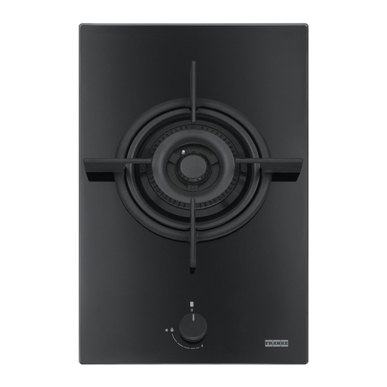
- Page 3 590x380x165mm NET weight 6,5 kg HOW IT LOOKS WHEN YOU RECEIVE IT…...
- Page 4 LABEL ON THE PACKAGING SERIAL NUMBER MODEL...
- Page 5 FHCR 301 1TC HE BK C 1 TRIPLE CROWN Parameter Value Dimensions (mm) Working dimensions (W x D) - 310 x 510 Power supply voltage / frequency220-240V, 50/60Hz Power / Current 0.6W / 16A Total installed gas rated power 4.00kW Total rated capacity - gas G20 0.381m3/h...
- Page 7 TRIPLE CROWN BURNER RATED POWER 4KW REDUCED POWER 1.8KW TC: Rated capacity G20 (m3/h) 0.381 Injectors G20 20mbar (100/mm): E(2x1,01) + I(1x0,68) TC :Rated capacity G30 / G31 (g/h)291 Injectors G30/G31 28-30/37mbar (100/mm) : E(2x0,68) + I(1x0,46) Red arrows FIXING POINT TO THE BURNER /CAP...
- Page 8 The use of larger pots than those specified can cause excessive overheating of the knobs and top and, in case of prolonged use, yellowing of the cover (if in stainless steel). Franke declines any liability for damage due to such use. CAST IORN GRID for triple crown WITH RUBBERS...
-
Page 9: Installation
INSTALLATION For fitted units, the components (plastic materials and veneered wood) must be assembled with heat-resistant adhesives (max. 100°C): Unsuitable materials and adhesives can result in warping and detachment. The use of hard wood decorative borders around the worktop behind the appliance is allowed, providing a minimum distance from the edge appliance 50 mm for the side wall,... - Page 10 GASKET FOR CONNECTION GAS 1/2 Hooks SCREW DRIVER FOR MINIMUM ADJUSTING sealing strip 2x5x2600mm In this picture dia of injectors is 101 marked always on the head of the injector LPG GAS INJECTORS : E(2x0,68) + I(1x0,46) CONNECTION GAS ½ MALE/FEMALE It is already fitted to the gas hose...
- Page 11 SERIAL NUMBER : I (Italy) P (COOKING HOB) 17 (PRODUCTION YEAR) J (MONTH:OCTOBER…) 57559 (PROGRESSIVE NUMBER CODE 106.0374.275 CERTIFICATE OF GUARANTEE SERIAL NUMBER FUN MODEL UNDER THE DRAW ER OF COOKING HOB...
-
Page 12: Lighting The Burners
LIGHTING THE BURNERS The hob is lit with the control knobs. To light the burners, proceed as follows: Press and turn the required knob to the lighting and max delivery position. Keep the knob pressed down for 3-4 seconds to allow the sparks to ignite the gas coming out the flme spreader and to allow the thermocouple to heat up. -
Page 13: Connection To Gas Supply
CONNECTION TO GAS SUPPLY Connect the appliance to the gas supply in compliance with the current regulations, only after making sure it is arranged for the type of gas to be used. Otherwise, carry out the operations described in the section on „replacing injectors”. -
Page 14: Replacing Injectors
REPLACING THE INJECTORS AND ADJUSTING THE MINIMUM REPLACING INJECTORS Important: all the appliances are factory-set for natural gas (G20). If a different type of gas is to be used, change the injectors as follows: Remove the grids, burner caps and flame-spreaders; Unscrew the injectors and replace them with those provided and suitable for the gas supply, making sure the marking matches that given in the table;... - Page 15 ADJUSTMENT SCREW THE MINIMUM FLAME Light the burners Remove the knobs (push-on type). Adjust the minimum flame by turning the adjustment screw clockwise to decrease the flame and anticlockwise to increase it. The screwdriver for adjustment is supplied with the accessories SCREWDRIVER FOR MINIMUM ADJUSTING GAS TAP VALVED...
-
Page 16: Replacing The Components
REPLACING THE COMPONENTS: ACCESSING THE HOB To access the tray containing the functional parts, proceed as follows: Remove the knobs ,grids, burner caps and unscrew the screws that fix all the burners to the hob... - Page 17 AS SPARE PART: GLASS WORKTOP (A) + BURNER GASKETS ( B )+ BURNERS PLATE ( C )
- Page 18 THE COOKING GAS HOB DRAWER TERMINAL BLOCK GAS CONNECTION BURNER GASKET TRIPLE CROWN WOK HOLDER BURNER WITH 3 INJECTORS G20- SUPPLIED WITH THERM. AND SPARK PLUG TRIPLE RING BURNER GENERATOR GAS TAP VALVED WITH MICROSWITCH...
- Page 19 REPLACING THERMOCOUPLE and SPARK PLUG of triple crown wok burner it is necessary remove the cooking hob from the furniture TRIPLE CROWN WOK HOLDER BURNER FOR MODEL W ITH 5 BURNERS WITH 3 INJECTORS G20- SUPPLIED W ITH THERM. AND SPARK PLUG PARK PLUG THERMOCOUPLE CONNECT TO THE GAS TAP VALVED Automatic Safety Valve: safety device that automatically closes the gas...
- Page 20 REPLACING GAS TAP VALVED AND MICROSWITCH Microswitch connect to The generator/lighting box THERMOCOUPLE DOUBLE CONNECTION Minimum adjusting screw Microswitch connect to the generator/lighting box MICROSWITCH CONNECTION TO GENERATOR BRACKET FIXING THE GAS TAP VALVED...
- Page 21 GAS HOB TROUBLESHOOTING FAILURE FAILURE DESCRIPTION FAILURE ELIMINATION The light does not work Electricity source If a power outage has occurred, you might want to check the plug or the socket source Electric ignition of gas burner functions -Water,detergent in the controls knobs -Disconnect the plug continuously -Microswitches are in not right position...
- Page 22 Thanks for your attention...
Need help?
Do you have a question about the FHCR 301 1TC HE BK C and is the answer not in the manual?
Questions and answers