Table of Contents
Advertisement
Quick Links
Advertisement
Table of Contents

Subscribe to Our Youtube Channel
Related Manuals for MR TAPMOTION MD-III


Summary of Contents for MR TAPMOTION MD-III
- Page 1 Motor-Drive Unit ® TAPMOTION MD-III Operating Instructions 3913897/02 EN...
- Page 2 © All rights reserved by Maschinenfabrik Reinhausen Dissemination and reproduction of this document and use and disclosure of its content are strictly prohibited unless expressly permitted. Infringements will result in liability for compensation. All rights reserved in the event of the granting of patents, utility models or designs.
-
Page 3: Table Of Contents
Table of contents Table of contents Introduction......................... 6 Validity .............................. 6 Manufacturer............................ 6 Subject to change without notice ...................... 6 Completeness............................. 6 Supporting documents........................ 7 Safekeeping............................ 7 Notation conventions .......................... 7 1.7.1 Symbols ................................ 7 1.7.2 Information system.............................. 8 1.7.3 Hazard communication system .......................... 8 Safety.......................... - Page 4 Table of contents Packaging, transport and storage .................. 23 Packaging ............................ 23 4.1.1 Suitability................................ 23 4.1.2 Markings................................ 23 Transportation, receipt and handling of shipments................ 24 Storage of shipments........................ 25 Unpacking shipments and checking for transportation damages ............. 26 Things to note when putting back into storage ................. 26 Fitting motor-drive unit ....................
- Page 5 Table of contents Fault elimination ....................... 56 13.1 General information .......................... 56 13.2 Fault elimination overview ........................ 57 Maintenance........................ 58 14.1 Maintenance intervals........................ 58 14.2 Taking on-load tap-changer out of service .................. 58 14.3 Maintaining motor-drive unit ...................... 59 14.4 Maintaining monitoring system ......................
-
Page 6: Introduction
1 Introduction 1 Introduction This technical file contains detailed descriptions on the safe and proper in- stallation, connection, commissioning and monitoring of the product. It also includes safety instructions and general information about the prod- uct. This technical file is intended solely for specially trained and authorized per- sonnel. -
Page 7: Supporting Documents
1 Introduction 1.5 Supporting documents The following documents also apply in addition to this technical file: ▪ Technical data and drawings which are provided upon order confirmation and delivery Also observe generally valid legislation, standards, and guidelines as well as specifications on accident prevention and environmental protection in the re- spective country of use. -
Page 8: Information System
1 Introduction Symbol Meaning Adapter ring Apply a coat of paint Use a file Grease Coupling bolt Use a ruler Use a saw Hose clip Wire eyelet, safety wire Use a screwdriver Table 1: Symbols 1.7.2 Information system Information is designed to simplify and improve understanding of particular procedures. - Page 9 1 Introduction 1.7.3.1 Warning relating to section Warnings relating to sections refer to entire chapters or sections, sub-sec- tions or several paragraphs within this technical file. Warnings relating to sections use the following format: Type and source of danger WARNING Consequences ►...
- Page 10 1 Introduction Pictogram Meaning Warning of combustible substances Warning of danger of tipping Table 3: Pictograms used in warning notices ® TAPMOTION MD-III 3913897/02 EN Maschinenfabrik Reinhausen GmbH 2019...
-
Page 11: Safety
2 Safety 2 Safety 2.1 General safety information The technical file contains detailed descriptions on the safe and proper in- stallation, connection, commissioning and monitoring of the product. ▪ Read this technical file through carefully to familiarize yourself with the product. -
Page 12: Personnel Qualification
2 Safety 2.4 Personnel qualification The product is designed solely for use in electrical energy systems and facili- ties operated by appropriately trained staff. This staff comprises people who are familiar with the installation, assembly, commissioning and operation of such products. 2.5 Operator's duty of care To prevent accidents, disruptions and damage as well as unacceptable ad- verse effects on the environment, those responsible for transport, installa-... -
Page 13: Protective Devices In The Motor-Drive Unit
2 Safety Always wear Protective clothing Close-fitting work clothing with a low breaking strength, with tight sleeves and with no protrud- ing parts. It mainly serves to protect the wearer against being caught by moving machine parts. Do not wear any rings, necklaces or other jew- elry. - Page 14 2 Safety ▪ Protection against accidental contact ▪ Electronics of monitoring system to monitor the vacuum interrupters in the on-load tap-changer ® TAPMOTION MD-III 3913897/02 EN Maschinenfabrik Reinhausen GmbH 2019...
-
Page 15: Product Description
3 Product description 3 Product description This chapter contains an overview of the design and function of the motor- drive unit and monitoring system. 3.1 Motor-drive unit 3.1.1 Function description of motor-drive unit The motor-drive unit adjusts the operating position of on-load tap-changers in regulating transformers to the individual operating requirements. -
Page 16: Design
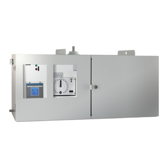
3 Product description Please note the following: 1. Check the shipment for completeness on the basis of the shipping docu- ments. 2. Store the parts in a dry place until installation. 3. The product must remain in its airtight, protective wrapping and may only be removed immediately before installation. - Page 17 3 Product description Spring lock Hand crank aperture with guide lever Front cover on swing frame Hand crank The front cover on the swing frame and the transmission gear cover plate ensure protection against accidental contact when the doors are open. 3.1.4.1 Indication field A clear indication field is fitted in the motor-drive unit.
-
Page 18: Monitoring System (Vim)
3 Product description The design of the motor-drive unit and panel heater ensures that air circu- lates inside the motor-drive unit and therefore that there is a constant interior temperature which is always higher than the outside temperature. 3.1.4.4 Swing frame/terminal rail The swing frame protects all electrical and mechanical parts of the motor- drive unit behind the swing frame against accidental contact. -
Page 19: Function Description Of Monitoring System
3 Product description 3.2.1 Function description of monitoring system WARNING Danger of death, severe injury and damage to property! Danger of death, severe injury and damage to property due to incorrect op- eration of hand crank and monitoring system! ► Never actuate on-load tap-changer with the hand crank if the transformer is energized. -
Page 20: Monitoring System Design
3 Product description 3.2.2 Monitoring system design Figure 3: Monitoring system (VIM), schematic diagram The monitoring system evaluates the current signals in the on-load tap- changer. For fail-safe transmission, the current signals are converted into optical signals and transferred via fiber-optic cables. The monitoring system carries out the following checks: 1. -
Page 21: Monitoring System Displays And Controls
3 Product description 3.2.3 Monitoring system displays and controls Figure 4: Monitoring system (VIM) displays and controls 1 Green TEST push-button 3 1 yellow and 1 red LED per phase for signaling errors 2 Green Power LED 4 Red RESET push-button The following displays and controls of the monitoring system (Vacuum Inter- rupter Monitoring VIM) are located behind the motor-drive unit's door: ▪... -
Page 22: Test Function
3 Product description 2. Press and hold the RESET push-button for around 6 seconds to disable the verification system for 10 hours. ð The 3 yellow LEDs on the monitoring circuit board flash slowly ð At the end of the 10 hours, the yellow LED go out and the unit returns to its normal function 3. -
Page 23: Packaging, Transport And Storage
4 Packaging, transport and storage 4 Packaging, transport and storage 4.1 Packaging The products are sometimes supplied with a sealed packaging and some- times also dried depending on what is required. A sealed packaging surrounds the packaged goods on all sides with plastic foil. -
Page 24: Transportation, Receipt And Handling Of Shipments
4 Packaging, transport and storage 4.2 Transportation, receipt and handling of shipments WARNING Danger of death and damage to property! Danger of death and damage to property due to tipping or falling load! ► Transport crate only when closed. ► Do not remove the mounting material used in the crate during transport. ►... -
Page 25: Storage Of Shipments
4 Packaging, transport and storage changer/de-energized tap-changer or contact Maschinenfabrik Rein- hausen GmbH to agree on how to proceed with drying. If this is not done, the packaged goods may be damaged. ▪ Name the damaged parts. Hidden damage When damages are not determined until unpacking after receipt of the ship- ment (hidden damage), proceed as follows: ▪... -
Page 26: Unpacking Shipments And Checking For Transportation Damages
4 Packaging, transport and storage If the product is installed more than 6 months after delivery, suitable mea- sures must be taken without delay. The following measures can be used: ▪ Correctly regenerate the drying agent and restore the sealed packaging. ▪... -
Page 27: Fitting Motor-Drive Unit
5 Fitting motor-drive unit 5 Fitting motor-drive unit 5.1 Preparatory work WARNING The motor-drive unit may be started by accident if the motor protective switch is not tripped! Risk of injury from starting the motor-drive unit by accident! ► Trip motor protective switch before starting to fit the drive shafts! NOTICE Damage to on-load tap-changer and motor-drive unit due to in- correct operation! - Page 28 5 Fitting motor-drive unit Checking neutral position Check the on-load tap-changer's neutral position with the door open as fol- lows: 1. Both change-over selector contacts are in the top position. Figure 5: Change-over selector contacts ® TAPMOTION MD-III 3913897/02 EN Maschinenfabrik Reinhausen GmbH 2019...
- Page 29 5 Fitting motor-drive unit 2. The adjustment markings on the by-pass switch are aligned to one an- other. Figure 6: Adjustment markings on the by-pass Check the motor-drive unit's neutral position as follows: 1. The tap position indicator is at neutral. 2.
-
Page 30: Fitting Motor-Drive Unit To On-Load Tap-Changer
5 Fitting motor-drive unit Assembly variants When assembling the motor-drive unit, a distinction is made between 2 vari- ants: 1. Standard assembly means that the motor-drive unit is fitted directly be- neath and secured to the on-load tap-changer. 2. Offset assembly (assembly on the floor) means that there is a gap be- tween the motor-drive unit and the on-load tap-changer beneath which it is fitted and that the motor-drive unit is secured to the transformer on the main tank. - Page 31 5 Fitting motor-drive unit To do so, proceed as follows: 1. Secure the two assembly plates supplied to the brackets below the on- load tap-changer oil compartment using the relevant fastening materials. Tightening torque: 60 ft·lb (80 Nm). Figure 9: Fitting assembly plates on on-load tap-changer 2.
- Page 32 5 Fitting motor-drive unit 4. Connect assembly plates with brackets on top of motor-drive unit housing. Tightening torque: 60 ft·lb (80 Nm). Figure 10: Fitting assembly plates on motor-drive unit Fitting drive shaft The drive shaft is the mechanical connection between the motor-drive unit and the on-load tap-changer.
- Page 33 5 Fitting motor-drive unit 4. Insert coupling bolt into shaft end on motor-drive unit. Slide square tube with coupling part on to coupling bolt. 5. Secure vertical drive shaft to drive. Tightening torque of screws: 7 ft·lb (9 Nm). Figure 11: Mounting drive shaft ®...
- Page 34 5 Fitting motor-drive unit 6. Secure drive shaft with coupling bolts and coupling brackets on shaft end of on-load tap-changer. Set a unilateral axial clearance of 0.12" (3 mm) between the coupling bolt and upper coupling piece. Tightening torque of screws: 7 ft·lb (9 Nm).
-
Page 35: Fitting Motor-Drive Unit To Transformer Tank
5 Fitting motor-drive unit 5.3 Fitting motor-drive unit to transformer tank If the motor-drive unit is supplied in the version for offset assembly, the drive housing is fitted on the main tank of the transformer. The on-load tap- changer and motor-drive unit are connected by a longer drive shaft in this in- stance. - Page 36 5 Fitting motor-drive unit The square shaft is supplied longer than required. During assembly it has to be cut to the desired length. Proceed as follows: 1. Ensure that the shaft ends to be connected are correctly aligned. The mo- tor-drive unit and on-load tap-changer unit must remain exactly in the as- sembly position during the entire drive shaft assembly process.
- Page 37 5 Fitting motor-drive unit 7. Secure vertical drive shaft to drive. Tightening torque of screws: 7 ft·lb (9 Nm). Figure 15: Mounting drive shaft ® Maschinenfabrik Reinhausen GmbH 2019 3913897/02 EN TAPMOTION MD-III...
- Page 38 5 Fitting motor-drive unit 8. Secure drive shaft with coupling bolts and coupling brackets on shaft end of on-load tap-changer. Set a unilateral axial clearance of 0.12" (3 mm) between the coupling bolt and upper coupling piece. Tightening torque of screws: 7 ft·lb (9 Nm).
-
Page 39: Installing Electrics For Motor-Drive Unit
5 Fitting motor-drive unit 5.4 Installing electrics for motor-drive unit WARNING Danger of death or severe injury! An energized transformer and energized on-load tap-changer components could cause death or serious injuries when installing the electrics! ► Adherence to the following safety precautions is mandatory. The drive may only be connected to circuits with an external overcurrent pro- tection device and isolating device with all poles disconnected so the equip- ment can be fully de-energized if required (service, maintenance etc.). - Page 40 5 Fitting motor-drive unit 6. Connect motor-drive unit following connection diagrams provided in the document pocket. Note the supply voltage stated in the connection dia- gram. 7. Connect main grounding conductor to grounding conductor terminal on terminal bar X1 (minimum connection cross-section 14 AWG (2.5 mm 8.
-
Page 41: Checks After Assembly
6 Checks after assembly 6 Checks after assembly Please contact Reinhausen Manufacturing if any aspect of the tests is not clear. 6.1 Preparations Danger of death and damage to property! WARNING Danger of death and damage to property due to electrical voltage! ►... - Page 42 6 Checks after assembly To perform tap-change operation tests and check the limit position locks, proceed as follows: 1. Switch on motor protective switch 8-2. ð The green Power LED on the monitoring circuit board lights up. 2. Ensure that the hand crank is in the storage bracket. 3.
-
Page 43: Testing Monitoring System
6 Checks after assembly 2. Return the on-load tap-changer to its adjustment position (display shows 3. Fit hand crank in bracket and close drive housing. 4. Exit maintenance mode by pressing the green TEST push-button on the monitoring system. 6.3 Testing monitoring system Figure 17: Monitoring system displays and control elements 1 Green TEST push-button 3 1 yellow and 1 red LED each for... - Page 44 6 Checks after assembly 2. Connect external source of power to busbar connection P2 and fixed con- tact A of one of the vacuum interrupter assemblies, e.g. left phase ð The power source must be able to produce a current of at least 20 A Figure 18: Vacuum interrupter assembly 3.
- Page 45 6 Checks after assembly Tighten nuts on access door to on-load tap-changer to a maximum tighten- ing torque of 11 ft·lb (15 Nm). ® Maschinenfabrik Reinhausen GmbH 2019 3913897/02 EN TAPMOTION MD-III...
-
Page 46: Drying Procedure
7 Drying procedure 7 Drying procedure NOTICE Damage to drive and on-load tap-changer! If the drive is dried in an autoclave, the drive and on-load tap-changer may be damaged. ► Do not dry drive in an autoclave. ► Remove the drive if the transformer is dried in an autoclave. ►... -
Page 47: Commissioning At The Transformer Manufacturer's Site
8 Commissioning at the transformer manufacturer's site 8 Commissioning at the transformer manufacturer's site WARNING Danger of death or severe injury! Danger of death or severe injury from explosive gases in the on-load tap- changer, in the pipework system, at the dehydrating breather opening and from flying parts and hot oil splashing! ►... -
Page 48: High-Voltage Tests On The Transformer
8 Commissioning at the transformer manufacturer's site 8.1 High-voltage tests on the transformer WARNING Danger of death or severe injury! Danger of death or severe injury from explosive gases in the on-load tap- changer, in the pipework system, at the dehydrating breather opening and from flying parts and hot oil splashing! ►... -
Page 49: Dielectric Tests On Transformer Wiring
8 Commissioning at the transformer manufacturer's site ▪ Leads used for testing must be removed before the high voltage test, as these function as antennas. ▪ Wherever possible, route the measurement and data leads separately from the energy cables. Contact the manufacturer if you have any questions about possible sources of danger. -
Page 50: Transporting Transformer To Installation Site
9 Transporting transformer to installation site 9 Transporting transformer to installation site WARNING Danger of death and severe injury! Danger of death or severe injury from explosive gases in the on-load tap- changer, in the pipework system, at the dehydrating breather opening and from flying parts and hot oil splashing! ►... -
Page 51: Commissioning Motor-Drive Unit At The Operating Site
10 Commissioning motor-drive unit at the operating site 10 Commissioning motor-drive unit at the operating site WARNING Danger of death and damage to property! Danger of death and damage to property due to electrical voltage! ► The relevant safety instructions must be observed. ►... - Page 52 10 Commissioning motor-drive unit at the operating site NOTICE Damage to the on-load tap-changer and motor-drive unit! Damage to on-load tap-changer and motor-drive unit due to incorrect use of position transmitter equipment! ► Only circuits stated in the chapter Technical data for position transmitter equipment [►Section 15.2, Page 61] may be connected to the position transmitter module connections.
-
Page 53: Actuating Motor-Drive Unit With Hand Crank
11 Actuating motor-drive unit with hand crank 11 Actuating motor-drive unit with hand crank WARNING Danger of death and severe injury! An energized transformer and energized on-load tap-changer components could cause death or serious injuries during hand crank operation! ► Switch off and lock transformer to prevent unintentional restart. ►... -
Page 54: Monitoring During Operation
12 Monitoring during operation 12 Monitoring during operation WARNING Danger of death or severe injury! Danger of death or severe injury from explosive gases in the on-load tap- changer, in the pipework system, at the dehydrating breather opening and from flying parts and hot oil splashing! ►... -
Page 55: Occasional Visual Checks
12 Monitoring during operation 3. Perform tap-change operation in opposite direction and then again press the green TEST push-button during the tap change. ð An alarm signal is generated, the motor-drive unit stops and returns to its starting position. 4. Press the red RESET push-button to reset the alarm status. 12.2 Occasional visual checks As well as the annual checks, perform occasional visual checks. -
Page 56: Fault Elimination
13 Fault elimination 13 Fault elimination 13.1 General information WARNING Danger of death or severe injury! Danger of death or severe injury from explosive gases in the on-load tap- changer, in the pipework system, at the dehydrating breather opening and from flying parts and hot oil splashing! ►... -
Page 57: Fault Elimination Overview
13 Fault elimination 13.2 Fault elimination overview The table below is intended to assist with detecting and, where possible, remedying faults. Contact Reinhausen Manufacturing for assistance if needed. Error pattern Action ▪ Error signaled on monitoring system ▪ Have on-load tap-changer and moni- by red or yellow LEDs toring system checked by trained per- sonnel... -
Page 58: Maintenance
MR or are otherwise suitably qualified to carry out the work. In such cases, we would ask you to forward to us a report on the mainte- nance performed so we can update our maintenance files. -
Page 59: Maintaining Motor-Drive Unit
14 Maintenance 6. Record the number of operations shown on the on-load tap-changer's op- erations counter. 14.3 Maintaining motor-drive unit After 500,000 tap-change operations, the braking contactor in the motor- drive unit must be replaced. Contact Reinhausen Maufacturing's Technical Service department. When maintaining the motor-drive unit, ensure the functions as per the Checks after assembly [►Section 6, Page 41] chapter. -
Page 60: Technical Data
15 Technical data 15 Technical data 15.1 Technical data for TAPMOTION® MD-III The technical data applies to the standard design and may vary depending on the design delivered. Subject to change without prior notice. MD-III motor-drive unit AC motor circuit voltage supply 208 V...240 V 120 V 220 V... -
Page 61: Technical Data For Position Transmitter Equipment
15 Technical data 15.2 Technical data for position transmitter equipment Resistance-type position transmitter module Standard resistance: 10.0 Ω (0.6 W, +/-1 %) per tap position The number of desired operating positions determines the number of loaded resistors. The decisive power loss of the position transmitter module is 0.6 W because in the worst-case scenario only one resistor is energized. - Page 64 Maschinenfabrik Reinhausen GmbH Falkensteinstrasse 8 93059 Regensburg +49 (0)941 4090-0 +49(0)941 4090-7001 sales@reinhausen.com www.reinhausen.com ® 3913897/02 EN - TAPMOTION MD-III - F0320702 - 08/19 - Maschinenfabrik Reinhausen GmbH 2019 THE POWER BEHIND POWER.
Need help?
Do you have a question about the TAPMOTION MD-III and is the answer not in the manual?
Questions and answers