
Related Manuals for Roberts R871


Summary of Contents for Roberts R871
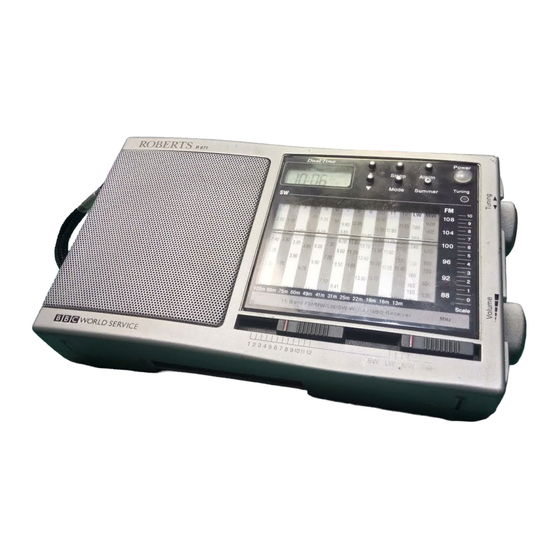
- Page 1 R871 15 Band FM/SW1-12/MW/LW Travel Alarm World Radio Please read this manual before use...
- Page 2 Controls 14 (on rear) 1. Clock display 5. Mode button 9. Tuning indicator 13. Shortwave selector 2. Forward button 6. Alarm button 10. Tuning control 14. Battery compartment (on rear) 3. Reverse button 7. Summer button 11. Volume control 15. DC input socket 4.
-
Page 3: Clock Display
Controls 17. Telescopic aerial 18. Snooze button 19. Key lock switch Clock display a. Summer time indicator f. Date display b. Time display g. Buzzer alarm indicator c. Snooze indicator h. Radio alarm indicator d. Day indicator i. Key lock indicator e. - Page 4 IMPORTANT Batteries The radio will not operate until the clock time and date are set. For Clock Operation Ensure that the “Lock” switch is set to the left hand “Unlocked” 1. Open the battery compartment (14) by sliding the cover in position before operation.
- Page 5 Setting the local time and date When the clock battery is first inserted the Hours and Minutes will flash in the clock display ready to be set. In this case proceed to step 2 below. If the clock time or date needs to be changed after the initial setting has taken place, start at step 1.
- Page 6 Setting the dual time and date 1. Press and release the “Mode” button to select the Dual Time mode. The Dual Time indicator will appear in the display. 2. Press and hold the “Mode” button for at least 5 seconds. The Hours and Minutes will flash in the display indicating that the Dual time can be adjusted.
-
Page 7: Setting The Alarm Time
Switching between local and dual time 1. Repeated presses on the “Mode” button will cause the clock to cycle between local and dual time modes. Dual time mode is indicated by the word “DUAL” in the clock display. Switching between summer and winter time 1. -
Page 8: Setting The Alarm Mode
Setting the alarm mode The alarm can be set so as to wake to Radio or Buzzer. Repeatedly press and release the “Alarm” button to cycle through the alarm modes. !Radio Alarm ! Buzzer Alarm ! Alarm Off ! " If the alarm is not required, set the alarm to Alarm off mode. -
Page 9: Operating The Radio
Operating the Radio 1. Press the “Power” button to turn on the radio. 2. Select the required waveband (SW/LW/MW/FM) with the “Waveband” selector. 3. Use the “Shortwave” selector to switch between the 12 shortwave bands (SW1 - SW12). 4. Rotate the “Tuning” control to select the desired station. The tuning indicator (4) will light up when the station is correctly tuned. - Page 10 Mains adaptor (not included) The AC adaptor for use with the R871 should provide 4.5 volts DC output at 300mA centre pin negative. Plug the adaptor into a mains outlet. Plug the lead from the adaptor into the “DC Socket”.
-
Page 11: Specifications
Specifications Aerial System LW : Built-in Ferrite aerial Power Requirements MW : Built-in Ferrite aerial Batteries FM : Telescopic aerial Clock :1.5V 1 x IEC LR6 (AA)size SW : Telescopic aerial Radio :4.5V 3 x IEC LR6 (AA)size Frequency Coverage External :4.5V 300mA (centre pin negative) - Page 12 Any claim under this guarantee should be made through the dealer from whom the instrument was purchased. It is likely that your Roberts dealer will be able to attend to any defect quickly and efficiently, but should it be necessary the dealer will return the instrument to the company’s service department for attention.
Need help?
Do you have a question about the R871 and is the answer not in the manual?
Questions and answers