Advertisement
Quick Links
FT2A-PWR US Series
AC Power Outlet Modules for FT2 Series
The Crestron® FT2A-PWR-US-1, FT2A-PWR-US-2, FT2A-PWR-US-3, and
FT2A-PWR-US-1-BASIC are modules designed for installation in Crestron FT2 FlipTop™
assemblies.
The outlet modules provide up to 3 NEMA AC power outlets on top of the table. An 8 ft
(2.44 m) three-prong power cord is fixed to the bottom of the module. The premium US power
modules (FT2A-PWR-US-1, FT2A-PWR-US-2, and FT2A-PWR-US-3) provide two under-the-
table receptacles for power switchers, HDBaseT transmitters, chargers, and other devices. Each
module is UL® Standards listed and is rated for 10 amps (total) at 125 V, 50/60 Hz. The following
table provides a size and feature comparison among models.
Module Model
Module Slots Required
Outlets on Top of the
FT2A-PWR-US-1
2
FT2A-PWR-US-2
3
FT2A-PWR-US-3
4
FT2A-PWR-US-1-BASIC
2
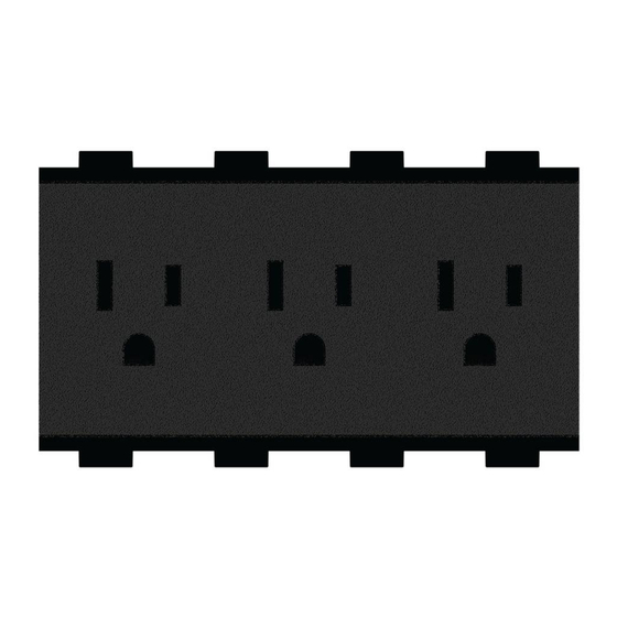
Below are illustrations of the FT2A-PWR-US-1-BASIC and an example of premium US power
modules. The premium US power modules (FT2A-PWR-US-1, FT2A-PWR-US-2, and
FT2A-PWR-US-3) are structurally similar.
FT2A-PWR-US-1-BASIC Module
Premium US Power Module (FT2A-PWR-US-2 shown)
Power outlet
module
Cord strain
relief
Power receptacle (2)
(18 in., 457 mm)
Power cord
(8 ft, 2.44 m)
Check the Box
Item
FT2A-PWR-US-1, FT2A-PWR-US-2, FT2A-PWR-US-3, or FT2A-PWR-US-1-BASIC
Install the Module
Outlets Beneath the
Install the power outlet module into the FT2 FlipTop assembly. If the bezel and locking bars have
Table
Table
not been installed on the FT2 FlipTop assembly, skip to step 6.
1
2
To install the power outlet module:
NOTE:
For ease of installation, install power outlet modules before installing any other module.
2
2
1.
Tap the lid retraction button to retract the one-touch lid, which disappears into the FT2
3
2
FlipTop assembly. If the assembly has two lids, open both.
1
None
2.
Remove and retain the magnetic bezel from the FT2 FlipTop assembly by grasping the
inside of the bezel and firmly pulling it up and away from the assembly until the magnetic
hold is broken.
3.
Using a manual torque screwdriver, unscrew and remove and retain the two locking bars on
either side of the module row where the module is to be installed.
NOTE:
In this example, an FT2A-PWR-US-2 power outlet module replaces three
preinstalled blank plate modules inside the FT2-700-ELEC (front row). The installation
process is identical for other power outlet modules, except for the number of module slots
Power outlet
required.
module
Remove Two Locking Bars
Power cable (2)
(10 in., 254 mm)
Power cord
4.
Lift and remove the modules you wish to replace.
(8 ft, 2.44 m)
5.
Insert the power cables through the empty module slots.
6.
Orient the module as shown in the following illustration and slide it down into the
appropriate module slots. Use the guide ribs on the front and rear of the module to help
position it in the assembly.
Qty
Position the Module (FT2A-PWR-US-2 shown)
1
7.
Confirm that all modules are level with their surroundings and place the locking bars
(removed in step 3) into position so that the screws on either side engage the screw holes
in the assembly.
8.
Using a manual torque screwdriver set to its lowest possible setting, hand tighten the
locking bar screws until the locking bars are secured to the FT2 FlipTop assembly.
9.
Place the bezel (removed in step 2) onto the FT2 FlipTop assembly so that the retractable
lid fits inside the bezel opening. The bezel is held in place using magnets.
Attach the Bezel to the Assembly
Locking
bars (3)
Lid
retraction
button
FT2A-PWR-US
Retractable lid
fits inside this
opening in bezel
Retractable lid
Advertisement

Related Manuals for Crestron FT2A-PWR US Series


Summary of Contents for Crestron FT2A-PWR US Series
- Page 1 Orient the module as shown in the following illustration and slide it down into the FT2A-PWR-US-1-BASIC are modules designed for installation in Crestron FT2 FlipTop™ appropriate module slots. Use the guide ribs on the front and rear of the module to help assemblies.
- Page 2 Crestron disclaims any proprietary interest in the marks and names of others. Crestron is not responsible for errors in typography or photography.