
Subscribe to Our Youtube Channel
Related Manuals for Alcatel OS6855-24


Summary of Contents for Alcatel OS6855-24
- Page 1 Part No. 060232-10, Rev. G August 2011 OmniSwitch 6855 Series Hardware Users Guide www.alcatel-lucent.com...
- Page 2 This user guide documents OmniSwitch 6855 Series hardware, including The specifications described in this guide are subject to change without notice. Copyright © 2010 by Alcatel-Lucent. All rights reserved. This document may not be reproduced in whole or in part without the express written permission of Alcatel-Lucent.
-
Page 3: Table Of Contents
OmniSwitch 6855-24 ...2-3 OmniSwitch 6855-U24 ...2-6 OmniSwitch 6855-U24X ...2-9 OmniSwitch 6855-14 ...2-12 OmniSwitch 6855-P14 ...2-15 OmniSwitch 6855-U10 ...2-18 Status LEDs ... 2-21 Rear Panel ...2-23 OS6855-24/OS6855-U24 ...2-23 OmniSwitch 6855 Series Hardware Users Guide ...ix ... 1-1 September 2011 ... 2-1... - Page 4 OS6855-U24X ...2-24 OS6855-14/P14 ...2-25 OS6855-U10 ...2-26 OS6855-24/U24/U24X Power Supplies ...2-27 PS-126I80AC Power Supply ...2-28 PS-I80AC-CC Power Supply ...2-29 PS-360I160AC-P Power Supply ...2-30 PS-120I80DC48 Power Supply ...2-31 PS-100I80DC24 Power Supply ...2-32 OS6855-14/P14/U10 Power Supplies ...2-33 PS-I40AC Power Brick ...2-34 PS-I66AC-P PoE Power Brick ...2-35 PS-I185AC-P (SDR-240-55) PoE Power Supply ...2-36...
- Page 5 Contents Chassis Air Convection for OS6855-U24X ...3-5 Installing Power Supplies ...3-6 Connecting a Power Supply Directly to the Chassis ...3-6 Rack Mounting the Power Supply Tray ...3-7 Connecting the Power Supply Cable ...3-9 Securing Power Supply Cord ...3-10 Hot-Swapping Power Supplies ...3-11 Hot-Swapping a Power Supply Directly Connected to the Chassis ...3-11 Hot-Swapping a Rack Mounted Power Supply ...3-12 Rack-Mounting the Chassis ...3-13...
- Page 6 Chapter 5 Booting 6855 Series Switches Booting an OmniSwitch 6855 ...5-1 Console Port ...5-2 Serial Connection Default Settings ...5-2 Modifying the Serial Connection Settings ...5-2 Viewing the Power Supply Status ...5-4 Monitoring the Chassis ...5-5 Checking the Overall Chassis Status ...5-5 Checking the Temperature Status ...5-5 Checking the Fan Status ...5-6 Checking the Power Supply Status ...5-6...
- Page 7 Contents Primary Management Module Selection ...7-7 Secondary Management Module Selection ...7-10 Idle Module Role ...7-12 Pass-Through Mode ...7-13 Recovering from Pass-Through Mode (Duplicate Slot Numbers) ...7-14 Stack Cabling ...7-17 Redundant Stacking Cable Connection ...7-18 Checking Redundant Stacking Cable Status ...7-19 Slot Numbering ...7-20 Dynamic Slot Number Assignment ...7-21 Manual Slot Number Assignment ...7-23...
- Page 8 Translated Safety Warnings ... A-8 Chassis Lifting Warning ... A-8 Blank Panels Warning ... A-8 Electrical Storm Warning ... A-8 Installation Warning ... A-9 Invisible Laser Radiation Warning ... A-9 Operating Voltage Warning ... A-9 Power Disconnection Warning ... A-10 Proper Earthing Requirement Warning ...
-
Page 9: About This Guide
This OmniSwitch 6855 Series Hardware Users Guide describes your switch hardware components and basic switch hardware procedures. Supported Platforms This information in this guide applies to the following products: • OmniSwitch 6855-24 • OmniSwitch 6855-U24 • OmniSwitch 6855-U24X • OmniSwitch 6855-14 •... - Page 10 Supported Platforms Unsupported Platforms The information in this guide does not apply to the following products: • OmniSwitch (original version with no numeric model name) • OmniSwitch 6600 Family • OmniSwitch 6800 Series • OmniSwitch 6850 Series • OmniSwitch 7700 •...
-
Page 11: Who Should Read This Manual
About This Guide Who Should Read this Manual? The audience for this users guide is network administrators and IT support personnel who need to config- ure, maintain, and monitor switches and routers in a live network. However, anyone wishing to gain knowledge on the OmniSwitch 6855 Series hardware will benefit from the material in this guide. -
Page 12: How Is The Information Organized
How is the Information Organized? How is the Information Organized? This users guide provides an overview of OmniSwitch 6855 Series switches, specifications of the hard- ware components, steps for setting up and managing OmniSwitch 6855 Series switches, and an overview and procedures for managing Power over Ethernet (PoE). - Page 13 About This Guide Stage 3: Integrating the Switch Into a Network Pertinent Documentation: Network Configuration Guide Advanced Routing Configuration Guide When you are ready to connect your switch to the network, you will need to learn how the OmniSwitch implements fundamental software features, such as 802.1Q, VLANs, and Spanning Tree. The Network Configuration Guide contains overview information, procedures and examples on how standard network- ing technologies are configured in the OmniSwitch 6855 Series.
-
Page 14: Related Documentation
Includes SFP and XFP transceiver specifications and product compatibility information. • Technical Tips, Field Notices Includes information published by Alcatel-Lucent’s Customer Support group. • Release Notes Includes critical Open Problem Re, feature exceptions, and other important information on the features supported in the current release and any limitations to their support. -
Page 15: Published / Latest Product Documentation
About This Guide Published / Latest Product Documentation All user guides for the OmniSwitch 6855 Series are included on the Alcatel-Lucent public website. This website also includes user guides for other Alcatel-Lucent Enterprise products. The latest user guides can be found on our website at: http://enterprise.alcatel-lucent.com/?dept=UserGuides&page=Portal... - Page 16 Technical Support page xvi OmniSwitch 6855 Series Hardware Users Guide About This Guide September 2011...
-
Page 17: Omniswitch Os6855 Family
1 OmniSwitch OS6855 Family The Alcatel-Lucent OmniSwitch 6855 family of fixed configuration LAN switches are industrial-grade, managed, Gigabit Ethernet units are designed to operate reliably in severe temperatures, as well as harsh physical and electrical conditions. Note. Stacking multiple OS6855 switches into a virtual chassis is only supported on the OS6855-U24X. -
Page 18: Chassis Configurations
OS6855-P14: Provides twelve (12) 10/100/1000 RJ-45 802.3af PoE ports and two (2) SFP ports. • OS6855-24: Provides twenty (20) 10/100/1000 RJ-45 ports and four (4) combo ports, with four of the 10/100/1000 RJ-45 ports supporting Power over Ethernet. Note. Power over Ethernet (PoE) is supported on OS6855-14, OS6855-P14 and OS6855-24 models only. -
Page 19: Security Features
OmniSwitch OS6855 Family • Supports a variety of fiber type, including single mode, multi-mode, bidirectional, and long haul optics allowing distances of up to 70 km. • Diverse power supply options, such as external, redundant, hot swappable, AC and DC •... -
Page 20: Availability Features
Availability Features Availability Features OmniSwitch 6855 switches incorporate advanced Alcatel-Lucent Operating System (AOS) protocols to ensure high availability for mission critical applications. Availability features are hardware- and software- based safeguards that help to prevent the loss of data flow in the unlikely event of a subsystem failure. -
Page 21: Hardware Monitoring
OmniSwitch OS6855 Family Hardware Monitoring Automatic Monitoring Automatic monitoring refers to the switch’s built-in sensors that automatically monitor operations. If an error is detected (e.g., over-threshold temperature), the switch immediately sends a trap to the user. The trap is displayed on the console in the form of a text error message. (In the case of an over-threshold temperature condition, the chassis displays an amber OK LED in addition to sending a trap.) LEDs LEDs, which provide visual status information, are provided on the chassis front panel. - Page 22 Availability Features OmniSwitch OS6855 Family page 1-6 OmniSwitch 6855 Series Hardware Users Guide September 2011...
-
Page 23: Chapter 2 Omniswitch 6855 Series Chassis And Hardware Components
2 OmniSwitch 6855 Series Chassis and Hardware OmniSwitch 6855 Chassis Configurations OmniSwitch 6855 Series switches are available in the chassis configurations shown in the table below: • OmniSwitch 6855-24 (OS6855-24) • OmniSwitch 6855-U24 (OS6855-U24) • OmniSwitch 6855-U24X (OS6855-U24X) • OmniSwitch 6855-14 (OS6855-14) •... - Page 24 OmniSwitch 6855 Chassis Configurations This chapter includes detailed information on these chassis types. Topics include: • OmniSwitch 6855 Series chassis descriptions • Technical specifications • Power Supplies • Power cords, console port, and pinout specifications page 2-2 OmniSwitch 6855 Series Chassis and Hardware Components OmniSwitch 6855 Series Hardware Users Guide September 2011...
-
Page 25: Omniswitch 6855-24
The OmniSwitch 6855-24 is an edge/workgroup switch offering 20 non-combo 10/100/1000Base-T, as well as four combo ports individually configurable to 10/100/1000Base-T or 1000Base-X high-speed connections. Additionally, the first four ports support PoE. The front panel of the OS6855-24 chassis contains the following major components: • System status LEDs •... - Page 26 Refer to the illustration below for more front panel information. For detailed LED descriptions, refer to page 2-21. For information on the chassis rear panel, refer to Console Port The OS6855-24 front panel pro- vides one RJ-45 port for console connections. Console connections are used by network administra- tors for switch management.
- Page 27 OmniSwitch 6855 Series Chassis and Hardware Components OS6855-24 Specifications Total non-combo 10/100/1000Base-T per switch (1–20) Total 802.3af PoE ports per switch (1–4) Total combo 10/100/1000Base- T combo per switch (21–24) Total combo SFP connectors per switch (21–24) Flash memory size...
-
Page 28: Omniswitch 6855-U24
OmniSwitch 6855-U24 OmniSwitch 6855-U24 The OmniSwitch 6855-U24 is an edge/workgroup switch offering 24 SFP connectors, and two combo ports individually configurable to 10/100/1000Base-T. The front panel of the OS6855-U24 chassis contains the following major components: • System status and slot indicator LEDs •... - Page 29 OmniSwitch 6855 Series Chassis and Hardware Components Refer to the illustration below for more front panel information. For detailed LED descriptions, refer to page 2-21. For information on the chassis rear panel, refer to 1000Mbps SFP The OS6855-U24 provides 22 non-combo SFP USB Port connectors (1–22) and 2 combo SFP connectors (24-24) for supported SFP transceivers.
- Page 30 OmniSwitch 6855-U24 OS6855-U24 Specifications Total non-combo SFP connec- tors per switch (1–22) Total combo SFP connectors per switch (23–24) Total combo 10/100/1000Base- T per switch (23–24) Flash memory size RAM memory size Chassis Width Chassis Height Chassis Height (rack units) Chassis Depth Chassis Weight Humidity (Operating and Stor-...
-
Page 31: Omniswitch 6855-U24X
OmniSwitch 6855 Series Chassis and Hardware Components OmniSwitch 6855-U24X The OmniSwitch 6855-U24X is an edge/workgroup switch offering 24 SFP connectors, two combo ports individually configurable to 10/100/1000Base-T and two 10 Gigabit SFP+ ports that can be configured as either stacking or uplink ports.. The front panel of the OS6855-U24X chassis contains the following major components: •... - Page 32 OmniSwitch 6855-U24X Refer to the illustration below for more front panel information. For detailed LED descriptions, refer to page 2-21. For information on the chassis rear panel, refer to Console Port The front panel provides one RJ-45 port for console con- nections.
- Page 33 OmniSwitch 6855 Series Chassis and Hardware Components OS6855-U24X Specifications Total non-combo SFP connec- tors per switch (1–22) Total combo SFP connectors per switch (23–24) Total combo 10/100/1000Base- T per switch (23–24) Total 10G SFP+ Stacking/ Uplink Ports (25-26) Flash memory size RAM memory size Chassis Width Chassis Height...
-
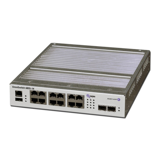
Page 34: Omniswitch 6855-14
OmniSwitch 6855-14 OmniSwitch 6855-14 The OmniSwitch 6855-14 is an edge/workgroup switch offering 12 10/100/1000 Base-T, and two SFP connectors. Additionally, the first four ports support PoE. The front panel of the OS6855-14 chassis contains the following major components: • System status and slot indicator LEDs •... - Page 35 OmniSwitch 6855 Series Chassis and Hardware Components Refer to the illustration below for more front panel information. For detailed LED descriptions, refer to page 2-21. For information on the chassis rear panel, refer to Console Port The OS6855-14 front panel pro- vides one RJ-45 port for console connections.
- Page 36 OmniSwitch 6855-14 OS6855-14 Specifications Total non-combo 10/100/ 000Base-T per switch (1–12) Total 802.3af PoE ports per switch (1–4) Total non-combo SFP connec- tors per switch (13–14) Flash memory size RAM memory size Chassis Width Chassis Height Chassis Height (rack units) Chassis Depth Weight Humidity (Operating and Stor-...
-
Page 37: Omniswitch 6855-P14
OmniSwitch 6855 Series Chassis and Hardware Components OmniSwitch 6855-P14 The OmniSwitch 6855-P14 is an edge/workgroup switch offering 12 10/100/1000 Base-T PoE ports, and two SFP connectors. The front panel of the OS6855-P14 chassis contains the following major components: • System status and slot indicator LEDs •... - Page 38 OmniSwitch 6855-P14 Refer to the illustration below for more front panel information. For detailed LED descriptions, refer to page 2-21. For information on the chassis rear panel, refer to Console Port Front panel provides one RJ-45 port for console connections. Console connections are used by network administrators for switch manage- ment.
- Page 39 OmniSwitch 6855 Series Chassis and Hardware Components OS6855-P14 Specifications Total non-combo 10/100/ 1000Base-T 802.3af ports (1–12) Total non-combo SFP connectors per switch (13–14) Flash memory size RAM memory size Chassis Width Chassis Height Chassis Height (rack units) Chassis Depth Weight Humidity (Operating and Storage) 0% to 95% non-condensing Operating Temperature Storage Temperature...
-
Page 40: Omniswitch 6855-U10
OmniSwitch 6855-U10 OmniSwitch 6855-U10 The OmniSwitch 6855-U10 is an edge/workgroup switch offering 8 SFP connectors, and two ports indi- vidually configurable to 10/100/1000Base-T. The front panel of the OS6855-U10 chassis contains the following major components: • System status and slot indicator LEDs •... - Page 41 OmniSwitch 6855 Series Chassis and Hardware Components Refer to the illustration below for more front panel information. For detailed LED descriptions, refer to page 2-21. For information on the chassis rear panel, refer to Console Port The OS6855-U10 front panel provides one RJ-45 port for con- sole connections.
- Page 42 OmniSwitch 6855-U10 OS6855-U10 Specifications Total non-combo SFP connec- tors per switch (1–8) Total non-combo 10/100/ 1000Base-T per switch (9–10) Flash memory size RAM memory size Chassis Width Chassis Height Chassis Height (rack units) Chassis Depth Weight Humidity (Operating and Stor- age) Operating Temperature Storage Temperature...
-
Page 43: Status Leds
OmniSwitch 6855 Series Chassis and Hardware Components Status LEDs LEDs provide visual status information. These “status lights” are used to indicate conditions, such as hardware and software status, primary role status, power supply status, fan and temperature errors, data speed, link integrity, and activity. Refer to the diagram below for detailed information on LED states. passed hardware diagnostic tests and the system software is operational. - Page 44 Status LEDs PRI (6855-U24X only) 10/100/1000 Ports SFP/SFP+ (Uplink Mode) Ports SFP+ Ports (Stacking Mode) Seven Segment LED page 2-22 OmniSwitch 6855 Series Chassis and Hardware Components State Description Solid Green Normal Operation Solid Amber Operating Temperature Exceeded Blinking Amber Operational but Auto- Configuration not successful Solid Green...
-
Page 45: Rear Panel
OmniSwitch 6855 Series Chassis and Hardware Components Rear Panel OS6855-24/OS6855-U24 The rear panel of OS6855-24/OS6855-U24 switches contains the following major components: • Two DB-25 connectors provided for primary and redundant power supplies. • Grounding block for type LCD8-10A-L grounding lug Note. -
Page 46: Os6855-U24X
Rear Panel OS6855-U24X The rear panel of OS6855-U24X switches contains the following major components: • Two DB-25 connectors provided for primary and redundant power supplies. • Grounding block for type LCD8-10A-L grounding lug • Two 10G SFP+ ports Note. The figure shows a pre-production version of the chassis without product, safety, and compliance information labels. -
Page 47: Os6855-14/P14
OmniSwitch 6855 Series Chassis and Hardware Components OS6855-14/P14 The rear panel of OS6855-14/P14 switch contains the following major components: • Two 3-pin connectors provided for primary and redundant system power supplies • Two 4-pin connectors provided for primary and redundant PoE power supplies •... -
Page 48: Os6855-U10
Rear Panel OS6855-U10 The rear panel of OS6855-U10 switch contains the following major components: • Two multi-contact connectors provided for primary and redundant power supplies. • Grounding block for type LCD8-10A-L grounding lug Note. The figure shows a pre-production version of the chassis without product, safety, and compliance information labels. -
Page 49: Os6855-24/U24/U24X Power Supplies
OmniSwitch 6855 Series Chassis and Hardware Components OS6855-24/U24/U24X Power Supplies • PS-126I80AC Power Supply (see • PS-I80AC-CC Power Supply (see • PS-360I160AC-P PoE Power Supply (see • PS-120I80DC48 - 48V DC Power Supply (see • PS-100I80DC24 - 24V DC Power Supply (see... -
Page 50: Ps-126I80Ac Power Supply
OS6855-24/U24/U24X Power Supplies PS-126I80AC Power Supply The PS-126I80AC Power Supply provides full system power for OmniSwitch 6855 Series switches and can be installed as either a primary or backup system power supply. P/S Component Model Provides System Power For Input Voltage Range... -
Page 51: Ps-I80Ac-Cc Power Supply
Maximum Output Power Output Voltage Output Current OmniSwitch 6855 Series Hardware Users Guide Fanless 80W AC Sytem Power Supply Description PS-I80AC-CC OS6855-24 and OS6855-U24/U24X 90 to 265 VAC 47 to 63 Hz 80 W 12.0 VDC (typical) 6.7 A (maximum) September 2011... -
Page 52: Ps-360I160Ac-P Power Supply
OS6855-24/U24/U24X Power Supplies PS-360I160AC-P Power Supply The PS-360I160AC-P Power Supply provides full system and Power over Ethernet (PoE) for the OmniSwitch 6855-24 and can be installed as either a primary or backup system and PoE power supply. P/S Component Model... -
Page 53: Ps-120I80Dc48 Power Supply
Output Voltage Output Current OmniSwitch 6855 Series Hardware Users Guide 80W, -48VDC System Power Supply Description PS-120I80DC48 OS6855-24 and OS6855-U24/U24X -36 to -72 VDC (-48 VDC Nominal Input) < 30A 80 W 12.0 VDC (typical) 6.7 A (maximum) September 2011... -
Page 54: Ps-100I80Dc24 Power Supply
OS6855-24/U24/U24X Power Supplies PS-100I80DC24 Power Supply The PS-100I80DC24 Power Supply provides full system power for OmniSwitch 6855 Series switches and can be installed as either the primary or backup system power supply. P/S Component Model Provides System Power For Input Voltage Range... -
Page 55: Os6855-14/P14/U10 Power Supplies
OmniSwitch 6855 Series Chassis and Hardware Components OS6855-14/P14/U10 Power Supplies • PS-I40AC - System Power Brick (see • PS-I66AC-P - PoE Power Brick (see • PS-I185AC-P (SDR-240-55) - PoE Power Supply (see Supply” on page 2-36) • PS-I40DC2448 - DC Power Brick (see •... -
Page 56: Ps-I40Ac Power Brick
OS6855-14/P14/U10 Power Supplies PS-I40AC Power Brick The PS-I40AC Power Brick provides full system power for the OmniSwitch 6855 Series switches and can be installed as either the primary or backup system power supply. P/S Component Model Provides System Power For Input Voltage Range Rated Frequency Inrush Current... -
Page 57: Ps-I66Ac-P Poe Power Brick
OmniSwitch 6855 Series Chassis and Hardware Components PS-I66AC-P PoE Power Brick The PS-I66AC-P PoE Power Brick provides Power over Ethernet for the OmniSwitch 6855-14 and can be installed as either the primary or backup PoE power supply. P/S Component Model Provides PoE Power For Input Voltage Range Rated Frequency... -
Page 58: Ps-I185Ac-P (Sdr-240-55) Poe Power Supply
OS6855-14/P14/U10 Power Supplies PS-I185AC-P (SDR-240-55) PoE Power Supply The PS-I185AC-P (SDR-240-55) PoE Power Supply provides Power over Ethernet for the OmniSwitch 6855-P14 and can be installed as either the primary or backup PoE power supply. P/S Component Model Provides PoE Power For Input Voltage Range Rated Frequency Maximum Output Power... -
Page 59: Ps-I40Dc2448 Power Brick
OmniSwitch 6855 Series Chassis and Hardware Components PS-I40DC2448 Power Brick The PS-I40DC2448 DC Power Brick provides full system power for the OmniSwitch 6855 Series switches and can be installed as either the primary or backup system power supply. P/S Component Model Provides System Power For Input Voltage Range... -
Page 60: Ps-I40Dc2448E Power Brick
OS6855-14/P14/U10 Power Supplies PS-I40DC2448E Power Brick The PS-I40DC2448E DC Power Brick provides full system power for the OmniSwitch 6855 Series switches and can be installed as either the primary or backup system power supply. P/S Component Model Provides System Power For Input Voltage Range Inrush Current Maximum Output Power... -
Page 61: Ps-75I42Dc48-P Poe Power Brick
OmniSwitch 6855 Series Chassis and Hardware Components PS-75I42DC48-P PoE Power Brick The PS-75I42DC48-P DC PoE Power Brick provides Power over Ethernet for the OmniSwitch 6855-14 and can be installed as either the primary or backup PoE power supply. P/S Component Model Provides PoE Power For Input Voltage Range... - Page 62 PS-I185AC-P (SDR-240-55) page 2-40 OmniSwitch 6855 Series Chassis and Hardware Components Products Supported OS6855-14, OS6855-U10 OS6855-P14 OS6855-14, OS6855-U10 OS6855-P14 OS6855-14 OS6855-14 OS6855-24, OS6855-U24 OS6855-U24X OS6855-24, OS6855-U24 OS6855-U24X OS6855-24, OS6855-U24 OS6855-U24X OS6855-24, OS6855-U24 OS6855-U24X OS6855-24 OS6855-P14 OmniSwitch 6855 Series Hardware Users Guide...
-
Page 63: Power Supply Shelf
OmniSwitch 6855 Series Chassis and Hardware Components Power Supply Shelf OS6855-24/U24 Alcatel-Lucent requires the use of the power supply shelf when connecting power supplies. The shelf can be attached directly to the back of the chassis or rack mounted. OS6855-14/U10 Alcatel-Lucent requires the use of the power supply shelf when connecting power supplies. -
Page 64: Stacking Cables
Stacking Cables Stacking Cables The following cables and transceivers can used for stacking switches into a virtual chassis. Depending on the length and stacking requirements, either copper or fiber can be used. Note. See Chapter 7, “Managing OmniSwitch 6855 Series Stacks,” OmniSwitch 6855 Series switches in a stacked configuration. -
Page 65: Ac Power Cords
OmniSwitch 6855 Series Chassis and Hardware Components AC Power Cords Since the power cord is the switch’s only disconnect device, it should be plugged into an easily accessible outlet. In the event that your power cord is lost or damaged, refer to the specifications below. Specifications The power cord included with this product contains three (3) insulated #18AWG stranded copper wires and is rated between 85-265 VAC (region dependent), 10 amps with a nominal length of 2 meters. -
Page 66: Dc Power Supply Considerations
DC Power Supply Considerations DC Power Supply Considerations In addition to the installation steps described in page 3-6 “Rack Mounting the Power Supply Tray” on page 3-7 ing additional considerations: • Connect to a -48V reliably grounded DC SELV source if using either a PS-120I80DC48 or PS- I40DC2448(E) power supply. -
Page 67: Installing Dc Power Source Wire Leads
OmniSwitch 6855 Series Chassis and Hardware Components A clamp inside each slot keeps the power wire tightly in place during operation. The DC power supply has side screws that can be used to remove the connector if required. Installing DC Power Source Wire Leads These instructions describe how to connect your 3-wire DC power source to the power connector on your DC power supply. -
Page 68: Chassis Grounding
DC Power Supply Considerations Tighten the clamp by tightening the screw above the slot into which you inserted the wire lead. The wire lead should be securely attached inside the connector. You should be able to pull on the wire and not dislodge it. -
Page 69: Installing The Ps-I185Ac-P (Sdr-240-55) Power Supply
Power Supply Label Protective Ground (PG) Parts Required Only parts provided by Alcatel-Lucent should be used when installing the power supply assembly. The PoE power supply uses both an input and output power cord with Removed Outer Jackets (ROJ): •... - Page 70 Installing the PS-I185AC-P (SDR-240-55) Power Supply Warning. Do not insert the NEMA 5-15 plug or IEC 60320 C15 power connector into the system power supply or any live power source until prompted to do so. Failure to follow these instructions may result in bodily injury and/or equipment damage.
-
Page 71: Final Power Cord Connections
OmniSwitch 6855 Series Chassis and Hardware Components To secure the standard portion of the "Y-type" or straight AC power cord, begin by inserting the BLACK (North America) or BROWN (International) wire into the Line (L) terminal located at the bottom-front of the PoE power supply. Next, insert the WHITE (North America) or BLUE (International) wire into the Neutral (N) terminal. - Page 72 Installing the PS-I185AC-P (SDR-240-55) Power Supply Note. See Chapter 4, “Mounting OS6855-14/P14 and OS6855-U10 Switches,” on mounting OmniSwitch 6855 Series switches. page 2-50 OmniSwitch 6855 Series Chassis and Hardware Components OmniSwitch 6855 Series Hardware Users Guide for additional information September 2011...
-
Page 73: Console Port
OmniSwitch 6855 Series Chassis and Hardware Components Console Port The console port, located on the chassis front panel, provides a console connection to the switch and is required when logging into the switch for the first time. By default, this RJ-45 connector provides a DTE console connection. -
Page 74: Port Pinouts
Port Pinouts Port Pinouts RJ-45 Console Port – Connector Pinout Pin Number Signals as DTE Console Port Ground Ground 10/100 Ethernet Port – RJ-45 Pinout (non-PoE) Pin Number Description not used not used not used not used Gigabit Ethernet Port – RJ-45 Pinout Pin Number Description BI_DB+... -
Page 75: 10/100/1000 Mbps Power Over Ethernet Port - Rj-45 Pinout
OmniSwitch 6855 Series Chassis and Hardware Components 10/100/1000 Mbps Power over Ethernet Port – RJ-45 Pinout Pin Number Description RX+ (-VDC) RX- (-VDC) TX+ (+VDC) TX- (+VDC) Overtemp Condition The OmniSwitch 6855 is designed to operate within a wider operating temperature range than normal network equipment as noted under the specifications section. - Page 76 Overtemp Condition OmniSwitch 6855 Series Chassis and Hardware Components page 2-54 OmniSwitch 6855 Series Hardware Users Guide September 2011...
-
Page 77: General Mounting Recommendations
3 Mounting OS6855-24 and Note. Never obstruct the air intake or exhaust vents located on the chassis. Obstructing these vents can cause switch failure. Always follow the recommended clearance values. General Mounting Recommendations Be sure that your switch is placed in a well-ventilated, static-free environment. Always allow adequate clearance at the front, rear, top, and sides of the switch. -
Page 78: Chapter 3 Mounting Os6855-24 And Os6855-U24/U24X
Reliable earthing of rack-mount equipment should be maintained. Particular attention should be given to supply connections other than direct connections to the branch circuit (e.g. use of power strips). page 3-2 Mounting OS6855-24 and OS6855-U24/U24X OmniSwitch 6855 Series Hardware Users Guide September 2011... -
Page 79: Air Flow Recommendations
Under extreme conditions a more frequent schedule may be required. Failure to maintain a regular filter maintenance schedule may cause particle build up resulting in restricted airflow and increased operating temperature. Refer to the Alcatel-Lucent price list for information on replace- ment filters. -
Page 80: Chassis Air Flow For Os6855-U24
This air flow provides required cooling for chassis components. page 3-4 Mounting OS6855-24 and OS6855-U24/U24X Air Intake Vent 3. Air Exhaust. The air flow is exhausted through the lou- vered fan exhaust vents at the top-rear of the chassis. -
Page 81: Chassis Air Convection For Os6855-U24X
Mounting OS6855-24 and OS6855-U24/U24X Chassis Air Convection for OS6855-U24X The OS6855-U24X switches are cooled by natural air convection, no forced air is required. Heatsink - Natural air convection over the heatsink. OmniSwitch 6855 Series Hardware Users Guide Fanless - Convection Cooled... -
Page 82: Installing Power Supplies
Carefully slide the power supply tray so that it is flush against the back of the chassis. Tighten the two captive screws located on the left and right sides of the power supply tray. page 3-6 Mounting OS6855-24 and OS6855-U24/U24X for more information. “Rack Mounting the Power Supply Tray”... -
Page 83: Rack Mounting The Power Supply Tray
Mounting OS6855-24 and OS6855-U24/U24X Carefully slide the power supply against the back of the chassis until the power connector securely connects. Tighten the captive screw for each power supply located at back of the power supply to the power supply tray. - Page 84 Once the screws at the bottom of each flange are secure, install the remaining rack mount screws. Be sure that all screws are securely tightened. page 3-8 Mounting OS6855-24 and OS6855-U24/U24X OmniSwitch 6855 Series Hardware Users Guide Tighten these screws to secure the power supply.
-
Page 85: Connecting The Power Supply Cable
Mounting OS6855-24 and OS6855-U24/U24X Connecting the Power Supply Cable Follow the steps below to connect a power supply with a cable: Be sure the chassis ( see “Rack-Mounting the Chassis” on page 3-13 securely fastened to the rack. Connect the proper end of the supplied power supply cable to the appropriately labeled primary or backup connector on the switch and tighten securely. -
Page 86: Securing Power Supply Cord
Secure the power cord retaining bracket to the power supply using the power supply screw removed in step 2 above. page 3-10 Mounting OS6855-24 and OS6855-U24/U24X Power Cord Retaining Bracket OmniSwitch 6855 Series Hardware Users Guide Use top hole to secure the power supply cord retaining bracket. -
Page 87: Hot-Swapping Power Supplies
Mounting OS6855-24 and OS6855-U24/U24X Hot-Swapping Power Supplies OmniSwitch 6855 Series switches support hot-swapping of their power supplies. The following sections describe how to hot-swap a power supply either directly connected (i.e., without a cable) or rack-mounted power supply. Warning: Before proceeding, ensure a redundant power supply is connected and operational. -
Page 88: Hot-Swapping A Rack Mounted Power Supply
Reconnect the power supply cable of the new power-supply and tighten securely. Re-connect the power supply to its power source. page 3-12 Mounting OS6855-24 and OS6855-U24/U24X Rack-Mounted Power Supplies OmniSwitch 6855 Series Hardware Users Guide September 2011... -
Page 89: Rack-Mounting The Chassis
19-inch rack-mount installations. These flanges must be attached to the chas- sis before the switch can be rack mounted. Note. If you are installing the switch in a 23-inch-wide rack, Alcatel-Lucent offers optional 23-inch rack- mounting hardware. For more information, contact your Alcatel-Lucent representative. •... - Page 90 Once the screws at the bottom of each flange are secure, install the remaining two rack mount screws. Be sure that all screws are securely tightened. page 3-14 Mounting OS6855-24 and OS6855-U24/U24X Attaching the Switch to the Rack OmniSwitch 6855 Series Hardware Users Guide...
-
Page 91: Table Mounting The Chassis
Mounting OS6855-24 and OS6855-U24/U24X Table Mounting the Chassis OmniSwitch 6855 Series switches can be installed freestanding as a tabletop unit. Note. Be sure that adequate clearance has been provided for chassis air flow and access to the front, back, and sides of the switch. For recommended clearances, refer to page 3-1. - Page 92 Mount the switch assembly on the table by inserting attachment screws through the flat portion of the mounting brackets and into the mounting surface. page 3-16 Mounting OS6855-24 and OS6855-U24/U24X Table Mounted OmniSwitch 6855 Series Hardware Users Guide CHASSIS ASSEMBLY...
-
Page 93: Chassis Components
4 Mounting OS6855-14/P14 and OS6855-U10 Switches This chapter covers different mounting and installation options for OS6855-14/P14 (PoE Models) and OS6855-U10 switches. Anti-Static Warning. Before handling any components, free yourself of static by wearing a grounding strap, or by grounding yourself properly. Static discharge can damage the switch and the backup power supply. -
Page 94: Chapter 4 Mounting Os6855-14/P14 And Os6855-U10 Switches
General Installation Recommendations General Installation Recommendations Cooling Recommendations The switches are cooled by natural air convection, no forced air is required. Reduced Air Flow Installation of the equipment in a rack should be such that the amount of air flow required for safe operation of the equipment is not compromised. -
Page 95: Recommended Clearances
Mounting OS6855-14/P14 and OS6855-U10 Switches Recommended Clearances Always allow adequate clearance at the front, rear, top, and sides of the switch. The following table shows the recommended minimum clearances for adequate chassis cooling and access to cabling and components at the front and rear of the chassis. Location OS6855-14/P14 0.875 inches (1/2 RU) for switches... -
Page 96: Power Supply Information
Power Supply Information Power Supply Information Before getting started, please note that OmniSwitch 6855 Series power supplies can be installed in a number of different configurations. For example: • Basic single system power, which provides minimum power requirements to the chassis, with no power supply redundancy/failover. -
Page 97: Rack-Mounting Os6855-14/P14 And Os6855-U10 Switches
It is recommended that two people install the switch assembly on the rack—one person to hold the chassis and position it on the rack, and a second person to secure the chassis to the rack using attachment screws. (Please note that Alcatel-Lucent does not provide rack-mount screws. Use the screws supplied by the rack vendor.) •... - Page 98 Rack-Mounting OS6855-14/P14 and OS6855-U10 Switches Mounting OS6855-14/P14 and OS6855-U10 Switches Attach the S-bracket that was removed at step 1 to the right-rear portion of the power supply tray, as shown. Use the single power supply tray attachment screw (provided). S-bracket Re-attach the S-bracket removed at step one to the power supply tray, as shown.
- Page 99 For OS6855-14 switches using redundant chassis power in addition to PoE, a total of four power supplies are required. For this configuration, plug a second Alcatel-Lucent-provided system power supply into the PS2 port on the rear panel of the chassis.
- Page 100 PoE Configurations (OS6855-P14) OS6855-P14 switches using PoE require a second power supply. This second power supply is a PoE- specific unit included with your Alcatel-Lucent product shipment and is installed into a separate power supply tray. Note. For OS6855-P14 switches the PoE power supply will be placed in a separate power supply tray.
- Page 101 Mounting OS6855-14/P14 and OS6855-U10 Switches Rack-Mounting OS6855-14/P14 and OS6855-U10 Switches Secure the retaining strap to the power supply tray using the attachment screws (provided). Retaining strap tabs Position the switch chassis immediately to the right of the power supply tray and attach the tray’s right- front mounting flange to the left-front chassis mounting flange using two attachment screws (provided).
- Page 102 Rack-Mounting OS6855-14/P14 and OS6855-U10 Switches Mounting OS6855-14/P14 and OS6855-U10 Switches Redundant Chassis Power with PoE (OS6855-14/P14) For switches using redundant chassis power with PoE, an additional power supply tray is required. This power supply tray is included with all shipments for which redundant chassis power and PoE have been specified as requirements.
- Page 103 Mounting OS6855-14/P14 and OS6855-U10 Switches Rack-Mounting OS6855-14/P14 and OS6855-U10 Switches Install one cord retainer bracket to the back of each installed power supply using the attachment screws (provided). Once all retainer clips are attached, place the slotted retainer clip over the bracket with the retainer fingers pointing down and slide the retainer bracket toward the power supply until it meets the power cord connector.
- Page 104 Rack-Mounting OS6855-14/P14 and OS6855-U10 Switches Mounting OS6855-14/P14 and OS6855-U10 Switches Once the holes are aligned, insert a rack mount screw (not provided) through the bottom hole of each flange. Tighten both screws until they are secure. When rack mounting, a clearance of 0.875 inches is recommended above OS6855-14 and OS6855-U10 switches.
-
Page 105: Dc-Poe Power Supply Mounting
Mounting OS6855-14/P14 and OS6855-U10 Switches Rack-Mounting OS6855-14/P14 and OS6855-U10 Switches DC-PoE Power Supply Mounting Due to the height of the DC PoE power supply it cannot be secured using the power supply retaining strap. Instead, it is secured directly to the power supply tray with screws. Additionally, a different power supply retaining strap is provided for securing the system power supply. -
Page 106: Ps-I185Ac-P (Sdr-240-55) Power Supply Mounting
Rack-Mounting OS6855-14/P14 and OS6855-U10 Switches Mounting OS6855-14/P14 and OS6855-U10 Switches PS-I185AC-P (SDR-240-55) Power Supply Mounting This power supply is used to provide PoE power to the OS6855-P14. Due to the height and physical char- acteristics of this power supply it cannot be secured using the power supply retaining strap. Instead, it is secured with a vented power supply cover as shown below. - Page 107 Mounting OS6855-14/P14 and OS6855-U10 Switches Rack-Mounting OS6855-14/P14 and OS6855-U10 Switches Place the vented power supply cover over the power supply and align the holes in the cover with the threaded holes in the tray. Before securing the cover to the tray, be sure to route the chassis output connector cable under the cover’s built-in retainer clip, as shown.
-
Page 108: Final Power Cord Connections
Rack-Mounting OS6855-14/P14 and OS6855-U10 Switches Mounting OS6855-14/P14 and OS6855-U10 Switches Secure the cover to the tray using three (3) attachment screws. Use the strain relief device to secure the power supply cord, as shown. Ensure the strain relief device firmly secures the cord and is mounted between the two notches to prevent any movement. Final Power Cord Connections Once the power supply has been secured to the tray, insert the output power cord’s four pin connector into the PoE power port located on the rear panel of the OS6855-P14 chassis. - Page 109 Mounting OS6855-14/P14 and OS6855-U10 Switches Rack-Mounting OS6855-14/P14 and OS6855-U10 Switches Note. See Chapter 2, “OmniSwitch 6855 Series Chassis and Hardware Components,” mation on installing power supplies. OmniSwitch 6855 Series Hardware Users Guide September 2011 for additional infor- page 4-17...
-
Page 110: Additional Rack Mounting Options
Rack-Mounting OS6855-14/P14 and OS6855-U10 Switches Mounting OS6855-14/P14 and OS6855-U10 Switches Additional Rack Mounting Options Depending on the number of power supplies, power supply trays, and chassis, the OS6855 can be mounted in a variety of ways as shown below. Redundant System and PoE Power Supplies - Side Mount Redundant System and PoE Power Supplies - Side/Rear Mount page 4-18 OmniSwitch 6855 Series Hardware Users Guide... - Page 111 Mounting OS6855-14/P14 and OS6855-U10 Switches Rack-Mounting OS6855-14/P14 and OS6855-U10 Switches Redundant System and PS-I185AC-P (SDR-240-55) Power Supplies - Side/Rear Mount OmniSwitch 6855 Series Hardware Users Guide September 2011 page 4-19...
-
Page 112: Table-Mounting Os6855-14/P14 And Os6855-U10 Switches
Table-Mounting OS6855-14/P14 and OS6855-U10 Switches Mounting OS6855-14/P14 and OS6855-U10 Switches Table-Mounting OS6855-14/P14 and OS6855- U10 Switches General Table-Mounting Guidelines OmniSwitch 6855 Series switches can be installed freestanding as tabletop-mounted units. If you will be table-mounting your switch(es), refer to the important guidelines below before installing. •... - Page 113 Mounting OS6855-14/P14 and OS6855-U10 Switches Table-Mounting OS6855-14/P14 and OS6855-U10 Switches Next, insert the two tabs at the base of the power supply tray into the slots provided at the bottom-rear portion of the switch chassis. Secure the power supply tray to the rear of the chassis using the attachment screws (provided).
- Page 114 OS6855-14 switches using PoE also require a second power supply. This second power supply is a PoE- specific unit included with your Alcatel-Lucent product shipment. Note. To distinguish PoE power supplies from standard system power supplies, note that PoE supplies have both a long and short connector cable hard-wired into the power supply brick, while standard system power supplies have only a single, long connector cable.
- Page 115 For OS6855-14 switches using redundant chassis power in addition to PoE, a total of four power supplies are required. For this configuration, plug a second Alcatel-Lucent-provided system power supply into the PS2 port on the rear panel of the chassis.
- Page 116 Table-Mounting OS6855-14/P14 and OS6855-U10 Switches Mounting OS6855-14/P14 and OS6855-U10 Switches Note. For switches using redundant chassis power with PoE, place the power supplies connected to the PS1 and PoE1 ports side-by-side in the tray. The power supplies connected to ports PS2 and PoE2 will be placed in an additional power supply tray later in the installation.
- Page 117 Mounting OS6855-14/P14 and OS6855-U10 Switches Table-Mounting OS6855-14/P14 and OS6855-U10 Switches retainer fingers pointing down and slide the retainer bracket toward the power supply until it meets the power cord connector. Insert two screws (provided) into the retainer clip slots and tighten until secure. Power supply If no additional power supplies are required, skip to step 11.
- Page 118 Table-Mounting OS6855-14/P14 and OS6855-U10 Switches Mounting OS6855-14/P14 and OS6855-U10 Switches Redundant Chassis Power with PoE (OS6855-14/P14) If the switch requires both redundant power and PoE, a minimum of four (4) power supplies is required (see page 4-4 for more information). To accommodate four power supplies, a second power supply tray must be installed directly behind the first power supply tray.
- Page 119 Mounting OS6855-14/P14 and OS6855-U10 Switches Table-Mounting OS6855-14/P14 and OS6855-U10 Switches Redundant Chassis Power with PoE/High PoE (OS6855-14/P14) For redundant chassis power with PoE configurations, attach two additional mounting brackets to the rear portion of the second power supply tray. If preferred, mount the complete switch assembly to the table by inserting attachment screws (not provided) through the flat portion of the mounting brackets and into the mounting surface.
-
Page 120: Industrial Environment Mounting Options
Industrial Environment Mounting Options Industrial Environment Mounting Options General Industrial Environment Mounting Guidelines • Wall-Mounting is supported on the OS6855-14, OS6855-P14, and OS6855-U10 in an industrial envi- ronment. • DIN rail mounting is supported on the OS6855-P14 in an industrial environment. •... -
Page 121: Wall Mounting Instructions
Mounting OS6855-14/P14 and OS6855-U10 Switches Wall Mounting Instructions Refer to the “General Wall-Mounting Guidelines” Use one person to securely hold the chassis assembly in position on the wall. Mark the location of the holes in the mounting brackets on the wall. Pre-drill the wall (if required). -
Page 122: Din Rail Mounting
Industrial Environment Mounting Options DIN Rail Mounting Before DIN rail mounting your equipment refer to the for additional mounting kits that may be required. DIN Rail Mounting - PS-I185AC-P (SDR-240-55) Power Supply The power supply has a factory-installed DIN bracket. To install the power supply, align the center of the power supply with the rail. -
Page 123: Din Rail Mounting - Ps-I40Ac System Power Supply
Mounting OS6855-14/P14 and OS6855-U10 Switches DIN Rail Mounting - PS-I40AC System Power Supply The PS-I40AC power supply requires a user installed DIN bracket. To install the power supply, use the three (3) attachment screws to secure the bracket to the power supply as shown in the diagram below. Attaching DIN Rail Racket to PS-I40AC Power Supply The DIN bracket has a spring-loaded clip under the bottom flange. -
Page 124: Din Rail Mounting - Chassis/Power Tray
Industrial Environment Mounting Options DIN Rail Mounting - Chassis/Power Tray Install the chassis brackets with the flange facing down. Align the holes of the rack mount flanges with the threaded holes in the DIN brackets. Attach the flanges to the brackets using the attachment screws (arrows on DIN brackets pointing to top of assembly). page 4-32 Mounting OS6855-14/P14 and OS6855-U10 Switches Attaching Chassis Brackets... - Page 125 Mounting OS6855-14/P14 and OS6855-U10 Switches The DIN brackets are spring-loaded on one side and the springs should be on the bottom. DIN Rail Bracket Attachment (Chassis removed for clarification) To attach the assembly to the DIN rail, align the center of the DIN brackets with the wall-mounted rail. OmniSwitch 6855 Series Hardware Users Guide Industrial Environment Mounting Options Spring-Loaded Clamp...
- Page 126 Industrial Environment Mounting Options Holding the assembly at a slight angle, press the DIN brackets against the rail, applying pressure to the springs. When the springs are depressed, press the assembly straight back against the rail until the brackets click into place. While grasping the chassis firmly, move the assembly slightly to test that all brackets are securely fastened to the rail.
-
Page 127: Hot-Swapping Power Supplies
Mounting OS6855-14/P14 and OS6855-U10 Switches Hot-Swapping Power Supplies Hot swapping is supported on OS6855 switches. In order to support the hot swapping of power supplies, the switch must have: • Redundant system power or redundant PoE power (if hot swapping a PoE supply) •... - Page 128 Hot-Swapping Power Supplies Carefully remove the retaining strap from the power supply tray. Be careful not to disrupt the operational power supply adjacent to the power supply being hot swapped. Attachment screw Lift the power supply that is being hot swapped out of the power supply tray and unplug its connector cable from the PS port located in the back of the switch chassis.
-
Page 129: Booting 6855 Series Switches
If any of the LED state differs from the states shown in the table above, refer to mation. Contact Alcatel-Lucent Customer Support if the LED state persists. For information on logging in and configuring your OmniSwitch 6855 Series switch, refer to the OmniSwitch 6855 Series Getting Started Guide. -
Page 130: Chapter 5 Booting 6855 Series Switches
Console Port Console Port The console port, located on the chassis front panel, provides a console connection to the switch and is required when logging into the switch for the first time. By default, this RJ-45 connector provides a DTE console connection. - Page 131 Booting 6855 Series Switches To change the stop bits value, enter boot serialstopbits, followed by the number of stop bits. Options include 1 (default) and 2. For example: Boot > boot serialstopbits 2 Verify your current changes by entering show at the boot prompt: Boot >...
-
Page 132: Viewing The Power Supply Status
Console Port Viewing the Power Supply Status The switch constantly monitors the power supply operation. If either the primary or backup power source (optional) unexpectedly shuts down, the switch sends out a notification to the user. In addition, the power LED on the chassis front panel displays solid amber. -
Page 133: Monitoring The Chassis
Booting 6855 Series Switches Monitoring the Chassis OmniSwitch 6855 Series switches can be monitored and managed via the console port using Command Line Interface (CLI) commands. The switches can also be monitored and managed via the Ethernet using CLI commands, WebView, SNMP, and OmniVista. The section below provides some examples of useful hardware-related monitoring CLI commands. -
Page 134: Checking The Fan Status
Monitoring the Chassis Checking the Fan Status To check the current status for all six fans in the chassis, use the -> show fan Chassis Fan Status -------+---+----------- Running Running Running Running For a complete list of output definitions for this command, refer to the OmniSwitch CLI Reference Guide. Checking the Power Supply Status For information on checking power supplies for OmniSwitch 6855 Series switches, refer to Series Switches”... -
Page 135: Using Leds To Visually Monitor The Chassis
Booting 6855 Series Switches Using LEDs to Visually Monitor the Chassis The front panel of OmniSwitch 6855 Series switches provides status LEDs that are useful in visually monitoring the status of standalone switches. Front panel LEDs include: • Ethernet Port LEDs •... - Page 136 Monitoring the Chassis Booting 6855 Series Switches page 5-8 OmniSwitch 6855 Series Hardware Users Guide September 2011...
-
Page 137: Chapter 6 Installing And Managing Power Over Ethernet (Poe)
Chapter 2, “OmniSwitch 6855 Series Chassis and Hardware Components,” OmniSwitch 6850 Series chassis. Important. Alcatel-Lucent recommends that PoE-enabled switches with attached IP telephones should have operational power supply redundancy at all times for 911 emergency requirements. In addition, both the switch and the power supply should be plugged into an Uninterruptible Power Source (UPS). -
Page 138: In This Chapter
Note. You can also monitor all chassis components and manage many chassis features, including Power over Ethernet, with WebView, Alcatel-Lucent’s embedded web-based device management application. WebView is an interactive and easy-to-use GUI that can be launched from the OmniVista or a web browser. -
Page 139: Power Over Ethernet Specifications
Installing and Managing Power over Ethernet (PoE) Power over Ethernet Specifications The table below lists general specifications for Alcatel-Lucent’s Power over Ethernet support. For more detailed power supply and Power Source Equipment (PSE) specifications, refer to “OmniSwitch 6855 Series Chassis and Hardware Components.”... -
Page 140: Dynamic Power Over Ethernet (Os6855-P14 Only)
Viewing PoE Power Supply Status Dynamic Power Over Ethernet (OS6855-P14 Only) This feature allows the OS6855-P14 to automatically adjust the maximm amount of PoE power based on the ambient temperature. In order to avoid an over temperature condition the OS6855-P14 will automati- cally reduce or increase the maximum amount of PoE power based on the following ambient temperatures: •... -
Page 141: Configuring Power Over Ethernet Parameters
September 2011 Default Value/Comments Disabled 15.4 Watts 80 Watts (OS6855-24) 66 Watts (OS6855-14) 185 Watts (OS6855-P14) Enabled command, you can reactivate command. To initially page 6-5... -
Page 142: Configuring The Total Power Available To A Port
Configuring Power over Ethernet Parameters Disabling PoE To disable PoE on a particular slot or port, use the To disable PoE on a specific PoE-capable port, enter a slot/port number. For example: -> lanpower stop 1/4 To disable PoE for all PoE-capable in a slot, enter the corresponding slot number only. For example: ->... -
Page 143: Setting Port Priority Levels
Installing and Managing Power over Ethernet (PoE) To increase or decrease the total power available to a slot, use the you are setting the power allowance for an individual slot, you must specify a slot number in the command line. For example, the syntax ->... -
Page 144: Understanding Priority Disconnect
Understanding Priority Disconnect Understanding Priority Disconnect The priority disconnect function differs from the port priority function described on applies only to the addition of powered devices (PDs) in tight power budget conditions. Priority discon- nect is used by the system software in determining whether an incoming PD will be granted or denied power when there are too few watts remaining in the PoE power budget for an additional device. -
Page 145: Priority Disconnect Is Enabled; Same Priority Level On All Pd
Installing and Managing Power over Ethernet (PoE) Priority Disconnect is Enabled; Same Priority Level on All PD Reminder. Priority disconnect examples are applicable only when there is inadequate power remaining to power an incoming device. When a PD is being connected to a port with the same priority level as all other in the slot, the physical port number is used to determine whether the incoming PD will be granted or denied power. -
Page 146: Priority Disconnect Is Disabled
Understanding Priority Disconnect Priority Disconnect is Disabled Reminder. Priority disconnect examples are applicable only when there is inadequate power remaining to power an incoming device. When priority disconnect is disabled, power will be denied to any incoming PD, regardless of its port priority status (i.e., low, high, and critical) or physical port number (i.e., 1/1). -
Page 147: Monitoring Power Over Ethernet Via Cli
Installing and Managing Power over Ethernet (PoE) Monitoring Power over Ethernet via CLI To monitor current PoE statistics and settings, use the displays a list of all current PoE-capable, along with the following information for each port: • Maximum power available to the port, in milliwatts •... - Page 148 Monitoring Power over Ethernet via CLI Installing and Managing Power over Ethernet (PoE) page 6-12 OmniSwitch 6855 Series Hardware Users Guide September 2011...
-
Page 149: Chapter 7 Managing Omniswitch 6855 Series Stacks
7 Managing OmniSwitch 6855 Series Stacks In addition to their working as individual stand-alone switches, OmniSwitch 6855 Series switches can also be linked together to work as a single virtual chassis known as a stack. With stacks, users can easily expand their switching capacity simply by adding additional switches to the stack. -
Page 150: In This Chapter
Note. You can also manage and monitor OmniSwitch 6855 Series stacks through WebView, Alcatel-Lucent’s embedded web-based device management application. WebView is an interactive and easy-to-use GUI that can be launched from OmniVista or a web browser. Please refer to WebView’s online documentation for more information. -
Page 151: Omniswitch 6855 Stacking Specifications
Managing OmniSwitch 6855 Series Stacks OmniSwitch 6855 Stacking Specifications The following table lists OmniSwitch 6855 Stacking specifications. Models Supporting Stacking Maximum Switches in a Stack Stacking Cable Lengths - Copper Stacking Cable Lengths - Fiber (SFP+) Stacking / Uplink Port Default Mode Changing to Stacking Mode The OmniSwitch 6855-U24X SFP+ ports can be set to either stacking or uplink mode. -
Page 152: Omniswitch 6855 Series Stack Overview
OmniSwitch 6855 Series Stack Overview OmniSwitch 6855 Series Stack Overview Users can configure OmniSwitch 6855-U24X switches into a single virtual chassis known as a stack. With stacks, switching capacity can be easily expanded simply by adding additional switches to the stack. For example, a user can start with a stack composed of two switches and add additional switches to that stack as network demands increase over time. - Page 153 Managing OmniSwitch 6855 Series Stacks Important Note. For management module redundancy to work effectively, the software on all switches operating in the stack must be synchronized at all times. Refer to page 7-37 for more information. Primary Secondary Idle Idle Offline Secondary Idle...
- Page 154 Roles Within the Stack Primary Secondary Offline Secondary Offline Primary Secondary Primary Redundant Management Module Failover (Two Switches) page 7-6 Managing OmniSwitch 6855 Series Stacks A stack of two OmniSwitches is operating normally. The stack consists of a primary module and a secondary module.
-
Page 155: Primary Management Module Selection
Managing OmniSwitch 6855 Series Stacks Primary Management Module Selection For a stack of OmniSwitches to operate as a virtual chassis, there must be a mechanism for dynamically selecting the switch within the stack that will assume the primary management role. OmniSwitches use three different methods for selecting the primary switch. - Page 156 Roles Within the Stack Using Saved Slot Information The saved slot number is the slot number the switch will assume following a reboot. This information is stored in a switch’s boot.slot.cfg file; the switch reads its slot number assignment from this file at bootup and assumes the specified slot number within the stack.
- Page 157 Managing OmniSwitch 6855 Series Stacks Using Switch Uptime A user can override both the MAC address and saved slot methods for determining a stack’s primary management module. This is done by controlling the uptime of switches in the stack. If all elements of a stack are powered off, the user can force a particular switch to become primary by powering on that switch and waiting a minimum of 15 seconds before powering on any other switches.
-
Page 158: Secondary Management Module Selection
Roles Within the Stack Secondary Management Module Selection In order to provide effective management module redundancy, all OmniSwitch stacked configurations dynamically assign a backup, or secondary, management module during the boot process. OmniSwitch stacks use two different methods for selecting the secondary switch. These methods are: •... - Page 159 Managing OmniSwitch 6855 Series Stacks Using Saved Slot Information If a stack with preassigned slot information for each switch is booted, the switch with the second lowest slot value is assigned the secondary management role. For example, if a stack of four switches is booted and the preassigned slot values for each switch are 1, 2, 3, and 4, the switch with the slot value of 2 is assigned the secondary role.
-
Page 160: Idle Module Role
Roles Within the Stack Idle Module Role Switches that are not assigned either the primary or secondary role in a stack are, by default, assigned the role of idle modules. These idle modules operate similarly to Network Interface (NI) modules in a chassis- based switch. -
Page 161: Pass-Through Mode
Managing OmniSwitch 6855 Series Stacks Pass-Through Mode The pass-through mode is a state in which a switch has attempted to join a stack but has been denied primary, secondary, and idle status. When a switch is in the pass-through mode, its Ethernet are brought down (i.e, they cannot pass traffic). -
Page 162: Recovering From Pass-Through Mode (Duplicate Slot Numbers)
Roles Within the Stack To avoid a pass-through condition following a reboot, make sure that all saved slot values for the stack are unique. Use the stack set slot slot 3 from 2 to 3: -> stack set slot 3 saved-slot 2 Use the show stack topology ->... - Page 163 Managing OmniSwitch 6855 Series Stacks To resolve this pass-through condition, simply assign slot 1001 a new saved slot value and reboot the module. This can be done in either of two ways: • Use the stack set slot command to assign the new value, then use the to reboot the module: ->...
- Page 164 Roles Within the Stack In some pass-through conditions (for example, larger stacks where multiple switches are in pass-through mode), it might be desirable to correct any duplicate saved slot assignments and then reboot the entire stack. The recovery from pass-through can be accomplished with fewer steps than reassigning slot numbers and rebooting modules on a slot-by-slot basis.
-
Page 165: Stack Cabling
Managing OmniSwitch 6855 Series Stacks Stack Cabling Switches in a stack are connected to each other with either copper or fiber stacking cables that are avail- able in various lengths. Fiber can be used with an SFP+ transceiver. Stacking cables for OmniSwitches can be connected in any pattern. In other words, the cable connected to stacking port A of one switch can be connected to either stacking port A or stacking port B of the adjacent switch. -
Page 166: Redundant Stacking Cable Connection
Stack Cabling Redundant Stacking Cable Connection OmniSwitches allow redundant stacking cable connections between the top-most and bottom-most switches in a stack. Important. For a stacked configuration to have effective redundancy, a redundant stacking cable must be installed between the upper-most and bottom-most switch in the chassis at all times. The figure below shows how the redundant connection between the top and bottom switches in the stack ensures that data will continue to flow throughout the stack, even in the event of a connection failure at one of the stacking cables. -
Page 167: Checking Redundant Stacking Cable Status
Managing OmniSwitch 6855 Series Stacks Redundant stacking cables provide a form of dual redundancy. As shown in the figure above, the redun- dant cable allows traffic to flow in the event of a stacking link failure. The redundant cable also provides failover if a switch goes down within the stack. -
Page 168: Slot Numbering
Slot Numbering Slot Numbering For a stack of OmniSwitches to operate as a virtual chassis, each module in the stack must be assigned a unique slot number. To view the current slot assignments for a stack, use the commands. The slot number is also displayed on the front panel of each switch by the LED located on the left side of the chassis (refer to There are two ways stacking modules are assigned slot numbers: •... -
Page 169: Dynamic Slot Number Assignment
Managing OmniSwitch 6855 Series Stacks Dynamic Slot Number Assignment Dynamic slot number assignment occurs when there are no boot.slot.cfg files present in the switches’ /flash directories. This is the case for new, “out of the box,” switches that have not been previously booted. - Page 170 Slot Numbering If the switch with the lowest MAC address happens to be the bottom-most module in the stack, slot numbering will not resume from the top of the stack. Instead, the system software will select the second- ary module using the standard method (i.e., the switch connected to the primary’s stacking port A), then continue to number the stack from the bottom up.
-
Page 171: Manual Slot Number Assignment
Managing OmniSwitch 6855 Series Stacks Manual Slot Number Assignment To manually assign slot numbers to one or more modules in a stack, use the command writes slot information to the boot.slot.cfg file located in a switch’s /flash directory. It is this saved slot information that the switch will assume following a reboot. -
Page 172: Reverting To The Dynamic Slot Numbering Model
Slot Numbering Because slot 6 is the top-most switch in the stack, it is reassigned the slot 1 (i.e., primary) position; because slot 7 is located immediately below slot 6, it is reassigned the slot 2 (i.e., secondary) position, etc. Note that the modules were not reloaded one-by-one, even though the stack set slot command provides optional syntax for doing so. -
Page 173: Hot-Swapping Modules In A Stack
Managing OmniSwitch 6855 Series Stacks Hot-Swapping Modules In a Stack As with chassis-based switches, NI modules within an OmniSwitch virtual chassis are hot-swappable. NI modules are essentially those modules operating in the stack in idle mode. These modules can be removed from, or added to, an existing stack without disrupting other modules in the stack. -
Page 174: Merging Stacks
Hot-Swapping Modules In a Stack Merging Stacks Merging stacks involves connecting two or more operational stacks and attempting to reboot them as a single virtual chassis. In most cases, errors will result. To merge stacks without causing errors, select one stack that is to remain up and running and then add modules from the other stack(s) by following the steps below: Make sure all switches are running the same software version. -
Page 175: Reloading Switches
Managing OmniSwitch 6855 Series Stacks Reloading Switches Reloading is essentially a soft boot of a switch. Users can reload stacked modules operating in any role— i.e., primary, secondary, idle, and pass-through. Refer to the sections below for more information. Reloading the Primary Management Module If the switch with the primary management role is reloaded, the switch with the secondary role automati- cally takes over primary management functions. - Page 176 Reloading Switches If there are only two switches in the stack, the switch that was reloaded (the former primary) assumes the secondary role when it comes back up. Primary - Slot 1 Secondary - Slot 2 -> reload primary Booting... Primary - Slot 2 Secondary - Slot 1 Primary - Slot 2...
-
Page 177: Reloading The Secondary Management Module
Managing OmniSwitch 6855 Series Stacks Reloading the Secondary Management Module If the switch with secondary management role is reloaded, the idle switch with the lowest slot number will automatically assume the secondary role. The reloaded switch (the former secondary) will assume an idle role when it comes back up. - Page 178 Reloading Switches If there are only two switches in the stack, the switch that was reloaded (the former secondary) resumes the secondary role when it comes back up. Primary - Slot 1 Secondary - Slot 2 -> reload secondary Primary - Slot 1 Booting...
-
Page 179: Reloading Switches With Idle Roles
Managing OmniSwitch 6855 Series Stacks Reloading Switches with Idle Roles Similar to reloading Network Interface (NI) modules on chassis-based switches, modules operating in idle status within a stack can be reloaded via the CLI. Note. Any traffic being passed on the module’s Ethernet will be interrupted during the reboot. Other modules within the stack will continue to operate without interruption. -
Page 180: Reloading All Switches In A Stack
Reloading Switches Reloading All Switches in a Stack Reloading all switches in the stack is essentially a full reboot of the virtual chassis. This can be useful in restoring a stack’s previously configured topology—i.e., the stack’s saved slot numbers and management roles. - Page 181 Managing OmniSwitch 6855 Series Stacks No Switches In the Stack Have Saved Slot Information If a full reload is issued and no switches in the stack have unique slot numbers, slot numbers will be assigned beginning with the switch with the lowest MAC address. (This can occur if the boot.slot.cfg file has been deleted from each switch’s /flash directory—e.g., by issuing the modules in the stack.) The switch with the lowest MAC address is assigned slot number 1 and given the primary management...
-
Page 182: Avoiding Split Stacks
Reloading Switches Avoiding Split Stacks The term “splitting” a stack refers to the creation of isolated modules within the virtual chassis. A split stack can result from the following conditions: • Two or more non-adjacent switches are reloaded simultaneously • The stack is reloaded without a redundant stacking cable connection The sections below offer simple guidelines for avoiding splitting the stack during the reload process. -
Page 183: Changing The Secondary Module To Primary
Managing OmniSwitch 6855 Series Stacks Changing the Secondary Module to Primary OmniSwitch stacks allow users to manually force the secondary switch to assume the primary manage- ment role. This is referred to as “takeover.” The behavior of a takeover is similar to that of reloading the primary management module (see Whenever a takeover is initiated, the switch with the secondary role automatically takes over primary management functions. - Page 184 Changing the Secondary Module to Primary If there are only two switches in the stack, the former primary switch resumes the secondary role when it comes back up following the takeover. Primary - Slot 1 Secondary - Slot 2 -> takeover Booting...
-
Page 185: Synchronizing Switches In A Stack
Managing OmniSwitch 6855 Series Stacks Synchronizing Switches in a Stack Management module synchronization refers to the process of copying all files in the /flash/working and /flash/certified directories of the primary management module to the /flash/working and /flash/certified directories of all the other switches in the stack. The system and configuration software on the non- primary switches—i.e., the secondary management module and any modules operating in idle—is over- written. -
Page 186: Monitoring The Stack
Monitoring the Stack Monitoring the Stack As shown in the previous sections, monitoring the current status and operation of all elements in a stack can help users avoid unexpected stack conditions. The table below includes CLI commands that are useful in monitoring stack conditions. -
Page 187: Cli Commands Supported On Both Primary And Secondary Management Modules
Managing OmniSwitch 6855 Series Stacks CLI Commands Supported on Both Primary and Secondary Management Modules Although most CLI commands are executed when logged into the switch with the primary management role, there is a group of commands that is supported when logged in to either the primary or secondary management module. - Page 188 Monitoring the Stack Managing OmniSwitch 6855 Series Stacks page 7-40 OmniSwitch 6855 Series Hardware Users Guide September 2011...
-
Page 189: Appendix A Regulatory Compliance And Safety Information
A Regulatory Compliance and Safety Information This appendix provides information on regulatory agency compliance and safety for OmniSwitch 6855 switches. Declaration of Conformity: CE Mark This equipment is in compliance with the essential requirements and other provisions of Directive 2004/108/EC (EMC), 2006/95/EC (LVD), 91/263/EEC (Telecom Terminal Equipment, if applicable), 1999/5/EC (R&TTE, if applicable) as amended by Directive 93/68/EEC (CE Mark Directive). -
Page 190: China Rohs: Hazardous Substance Table
对销售之日的所售产品, 本表显示, 阿尔卡特朗讯公司供应链的电子信息产品可能包含这些物质。注意: 在所售产 品中可能会也可能不会含有所有所列的部件。 This table shows where these substances may be found in the supply chain of Alcatel-Lucent electronic information products, as of the date of sale of the enclosed product. Note that some of the component types listed above may or may not be a part of the enclosed product. - Page 191 Regulatory Compliance and Safety Information China RoHS: Hazardous Substance Table Products are packaged using one or more of the following packaging materials: Corrugated Cardboard Corrugated Fiberboard Low-Density Polyethylene OmniSwitch 6855 Hardware Users Guide September 2011 page A-3...
-
Page 192: Standards Compliance
Standards Compliance Standards Compliance The product bears the CE mark. In addition it is in compliance with the following other safety and EMC standards: All hardware switching modules used in an OmniSwitch 6855 switch comply with Class A standards. Modules with copper connectors meet Class A requirements using unshielded (UTP) cables. Safety Standards •... -
Page 193: Fcc Class A, Part 15
RS101, RS103 1. The OmniSwitch 6855-P14 does not meet this military shock and vibration standard. 2. Contact Alcatel-Lucent for availability. FCC Class A, Part 15 This equipment has been tested and found to comply with the limits for Class A digital device pursuant to Part 15 of the FCC Rules.These limits are designed to provide reasonable protection against harmful... -
Page 194: Canada Class A Statement
Standards Compliance If this equipment does cause interference to radio or television reception, the user is encouraged to try to correct the interference by one or more of the following measures: • Reorient the receiving antenna. • Relocate the equipment with respect to the receiver. •... -
Page 195: Class A Warning For Taiwan And Other Chinese Markets
Regulatory Compliance and Safety Information Class A Warning for Taiwan and Other Chinese Markets This is a Class A Information Product. When used in a residential environment, it may cause radio frequency interference. Under such circumstances, the user may be requested to take appropriate countermeasure. -
Page 196: Translated Safety Warnings
Translated Safety Warnings Translated Safety Warnings Chassis Lifting Warning Two people are required when lifting the chassis. Due to its weight, lifting the chassis unassisted can cause personal injury. Also be sure to bend your knees and keep your back straight when assisting with the lifting of the chassis. -
Page 197: Installation Warning
Regulatory Compliance and Safety Information Installation Warning Only personnel knowledgeable in basic electrical and mechanical procedures should install or maintain this equipment. Français: Toute installation ou remplacement de l'appareil doit être réalisée par du personnel qualifié et compétent. Deutsch: Dieses Gerät soll nur von Personal installiert oder gewartet werden, welches in elektrischen und mechanischen Grundlagen ausgebildet ist. -
Page 198: Power Disconnection Warning
Translated Safety Warnings Power Disconnection Warning Your switch is equipped with multiple power supplies. To reduce the risk of electrical shock, be sure to disconnect all power connections before servicing or moving the unit. Français: Il se peut que cette unité soit équipée de plusieurs raccordements d'alimentation. Pour supprimer tout courant électrique de l'unité, tous les cordons d'alimentation doivent être débranchés. -
Page 199: Dc Power Supply Connection Warning
Regulatory Compliance and Safety Information DC Power Supply Connection Warning For EMC/EMI, each DC/DC power supply requires that the ground wire is connected from each DC/DC power supply to Common Earth Ground. Français: Pour EMC/EMI, pour chaque alimentation DC/DC, il est impératif que le fil de terre soit branché... -
Page 200: Wrist Strap Warning
Français: L'électricité statique (ESD) peut endommager les composants du commutateur. Pour cette raison Alcatel-Lucent joint à l'envoi du châssis un bracelet antistatique à brancher sur la prise mise à la terre située en bas à droite du commutateur. Vous devrez mettre ce bracelet avant toute intervention hardware. -
Page 201: Instrucciones De Seguridad En Español
Deseche las baterías usadas según las instrucciones del fabricante. Las instrucciones del fabricante son como sigue: Devuelva el módulo con la batería del litio a Alcatel-Lucent. La batería del litio será substituida en la fábrica de Alcatel-Lucent. -
Page 202: Advertencia Sobre Una Apropiada Conexión A Tierra
Para este propósito, Alcatel-Lucent proporciona una pulsera antiestática y un terminal que pone a tierra situados cerca de la parte superior derecha del chasis. Para que la pulsera antiestática sea eficaz en la eliminación de ESD, las fuentes de alimentación se deben instalar en el chasis y enchufar en las salidas de CA con descarga a... -
Page 203: Index
3-4, 3-5 booting monitoring OS6855-24 front panel OS6855-U10 front panel 2-18 OS6855-U24 front panel 2-6, 2-9, 2-12, 2-15 rear panel 2-23 chassis types OS6855-24 OS6855-U10... - Page 204 power cord specifications 2-43 power cords 2-42, 2-43 Power on LAN see PoE Power over Ethernet see PoE Power over LAN see PoE power supplies PS-126I80AC AC power supply 2-28 power supply connecting a DC power source 2-44 power supply shelf 2-41 primary management module dynamic selection...
Need help?
Do you have a question about the OS6855-24 and is the answer not in the manual?
Questions and answers