
Related Manuals for Makita GWT04


Summary of Contents for Makita GWT04
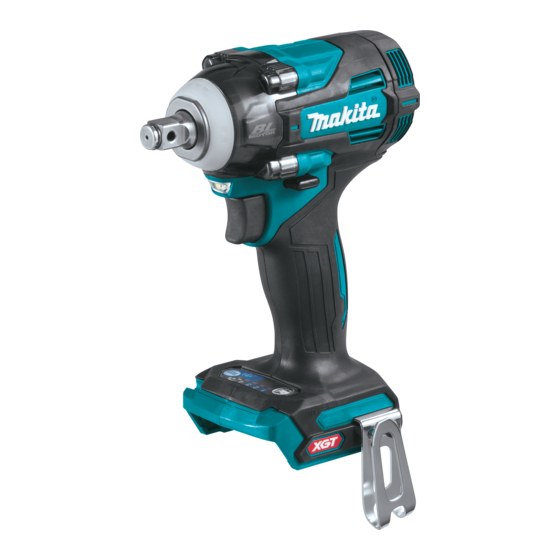
- Page 1 INSTRUCTION MANUAL MANUAL DE INSTRUCCIONES Cordless Impact Wrench Llave de Impacto Inalámbrica GWT04 GWT05 IMPORTANT: Read Before Using. IMPORTANTE: Lea antes de usar.
-
Page 2: Specifications
ENGLISH (Original instructions) SPECIFICATIONS Model: GWT04 GWT05 Fastening capacities Standard bolt M10 - M20 (3/8″ - 3/4″) High tensile bolt M10 - M16 (3/8″ - 5/8″) Square drive 12.7 mm (1/2″) No load speed (RPM) Max impact mode 0 - 3,200 /min... - Page 3 Do not abuse the cord. Never use the cord for Power tool use and care carrying, pulling or unplugging the power tool. Do not force the power tool. Use the correct Keep cord away from heat, oil, sharp edges power tool for your application. The correct or moving parts.
- Page 4 Do not use a battery pack or tool that is dam- Symbols aged or modified. Damaged or modified batteries may exhibit unpredictable behaviour resulting in The followings show the symbols used for tool. fire, explosion or risk of injury. Do not expose a battery pack or tool to fire or volts excessive temperature.
-
Page 5: Functional Description
If you can see the red indicator on the causing fires, personal injury and damage. It will upper side of the button, it is not locked completely. also void the Makita warranty for the Makita tool and charger. CAUTION: Always install the battery cartridge fully until the red indicator cannot be seen. -
Page 6: Overheat Protection
This tool is equipped with an electric brake. If the tool 75% to 100% consistently fails to quickly stop after the switch trigger is released, have the tool serviced at a Makita service center. 50% to 75% Lighting up the front lamp... - Page 7 Reversing switch action ► 1. Button To turn on the lamp status, press the button for one ► 1. Reversing switch lever second. To turn off the lamp status, press the but- for one second again. CAUTION: Always check the direction of With the lamp status ON, pull the switch trigger to turn rotation before operation.
-
Page 8: Changing The Application Mode
Changing the application mode Changing the impact force You can change the impact force in four steps: 4 (max), 3 (hard), 2 (medium), and 1 (soft). This allows a tightening suitable to the work. The level of the impact force changes every time you press the button You can change the impact force within approximately one minute after releasing the switch trigger. - Page 9 Example of application Application mode Example of application (Impact force grade displayed on panel) 4 (Max) Assembling steel frames and tightening long screws or bolts. 3 (Hard) Assembling steel frames. 2 (Medium) Assembling or disassembling scaffolds and frameworks. 1 (Soft) Assembling furniture.
- Page 10 Changing the application mode This tool employs several easy-to-use application modes for driving bolts with good control. The type of the application mode changes every time you press the button You can change the application mode within approximately one minute after releasing the switch trigger. NOTE: You can extend the time to change the application mode approximately one minute if you press the but- Application mode Feature...
- Page 11 Tool with the ring spring Full speed mode For GWT04 For impact socket without O-ring and pin ► 1. Button 2. Lamp When full speed mode is turned on, the tool speed ►...
-
Page 12: Operation
Tool with the detent pin OPERATION For GWT05 CAUTION: Always insert the battery cartridge all the way until it locks in place. If you can see the red indicator on the upper side of the button, it is not locked completely. Insert it fully until the red indicator cannot be seen. -
Page 13: Maintenance
To maintain product SAFETY and RELIABILITY, (89) (1/2") repairs, any other maintenance or adjustment should (59) be performed by Makita Authorized or Factory Service (30) Centers, always using Makita replacement parts. OPTIONAL 1. Fastening time (second) 2. Fastening torque ACCESSORIES NOTE: Hold the tool pointed straight at the bolt or nut. -
Page 14: Especificaciones
ESPAÑOL (Instrucciones originales) ESPECIFICACIONES Modelo: GWT04 GWT05 Capacidades de fijación Perno estándar 10 mm - 20 mm (3/8″ - 3/4″) Perno de alta resistencia 10 mm - 16 mm (3/8″ - 5/8″) Adaptador cuadrado 12,7 mm (1/2″) Velocidad sin carga (RPM) Modo de impacto máx. - Page 15 Seguridad eléctrica Retire cualquier llave de ajuste o llave de apriete antes de encender la herramienta. Una Las clavijas de conexión de las herramientas llave de ajuste o llave de apriete que haya sido eléctricas deberán encajar perfectamente en la dejada puesta en una parte giratoria de la herra- toma de corriente.
- Page 16 Mantenga las herramientas de corte limpias y Siga las instrucciones para la lubricación y filosas. Si recibe un mantenimiento adecuado y cambio de accesorios. tiene los bordes afilados, es probable que la herra- No modifique ni intente reparar el aparato ni el mienta se atasque menos y sea más fácil controlarla.
- Page 17 Asimismo, esto inva- ya no sirva en absoluto. El cartucho de batería lidará la garantía de Makita para la herramienta y el puede explotar si se tira al fuego. cargador Makita.
-
Page 18: Descripción Del Funcionamiento
Sistema de protección para la DESCRIPCIÓN DEL herramienta/batería FUNCIONAMIENTO La herramienta está equipada con un sistema de pro- tección para la herramienta/batería. Este sistema corta PRECAUCIÓN: Asegúrese siempre de que la automáticamente la alimentación para prolongar la vida herramienta esté apagada y el cartucho de batería de la herramienta y la batería. - Page 19 La herramienta está equipada con un freno eléctrico. Si Cargar la la herramienta falla constantemente en detenerse tras batería. soltar el gatillo interruptor, lleve la herramienta a mante- La batería nimiento a un centro de servicio Makita. pudo haber funcionado Iluminación de la luz delantera mal. PRECAUCIÓN:...
- Page 20 NOTA: Para confirmar el estado de la lámpara, jale el gatillo. Cuando la lámpara se enciende al jalar el gatillo interruptor, el estado de la lámpara está acti- vado. Cuando la lámpara no se enciende, el estado de la lámpara está desactivado. NOTA: Cuando la herramienta se sobrecalienta, la luz parpadea durante un minuto, y luego la pantalla LED se desactiva.
- Page 21 Cambio del modo de aplicación Cambio de la fuerza de impacto Usted puede cambiar la fuerza de impacto a cuatro niveles: 4 (máx.), 3 (dura), 2 (media) y 1 (suave). Esto permite un apriete adecuado para el trabajo. El nivel de la fuerza de impacto cambia cada vez que presiona el botón Usted puede cambiar la fuerza de impacto dentro de aproximadamente un minuto después de haber soltado el gatillo interruptor.
- Page 22 Ejemplo de aplicación Modo de aplicación Ejemplo de aplicación (Grado de fuerza del impacto mostrado en el panel) 4 (Máx.) Ensamble de armazones de acero y apriete de tornillos o pernos largos. 3 (duro) Ensamble de los armazones de acero. 2 (medio) Ensamble o desensamble de andamios y bastidores.
- Page 23 Cambio del modo de aplicación Esta herramienta emplea varios modos de aplicación fáciles de usar para insertar pernos con un buen control. El tipo de modo de aplicación cambia cada vez que presiona el botón Usted puede cambiar el modo de aplicación dentro de aproximadamente un minuto después de haber soltado el gatillo interruptor. NOTA: Usted puede extender el tiempo para cambiar el modo de aplicación en aproximadamente un minuto si oprime el botón Modo de aplicación Característica...
- Page 24 2. Lámpara Herramienta con el resorte de anillo Cuando se activa el modo de velocidad máxima, la Para el modelo GWT04 velocidad de la herramienta se vuelve más rápida Para dados de impacto sin anillo en O ni pasador incluso si no aprieta el gatillo interruptor por completo.
-
Page 25: Operación
Saque el anillo en O fuera de la ranura en el dado El gancho resulta útil para colgar temporalmente la de impacto y retire el pasador del dado de impacto. herramienta. Se puede instalar en cualquiera de los Coloque el dado de impacto en el adaptador cuadrado lados de la herramienta. -
Page 26: Mantenimiento
(59 ft•lbs) tenimiento o ajuste deberán ser realizadas en centros 40 N•m (30 ft•lbs) de servicio autorizados o de fábrica Makita, empleando siempre repuestos Makita. ACCESORIOS 1. Tiempo de apriete (segundos) 2. Torsión de apriete OPCIONALES NOTA: Sujete la herramienta orientada en línea recta... - Page 28 Para reducir la exposición a estos productos químicos: trabaje en un área bien ventilada y póngase el equipo de seguridad indicado, tal como las máscaras contra polvo que están especialmente diseñadas para filtrar partículas microscópicas. Makita Corporation 3-11-8, Sumiyoshi-cho, Anjo, Aichi 446-8502 Japan 885804-946...
Need help?
Do you have a question about the GWT04 and is the answer not in the manual?
Questions and answers