
Subscribe to Our Youtube Channel
Related Manuals for Makita GPP01


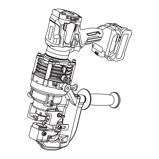
Summary of Contents for Makita GPP01
- Page 1 INSTRUCTION MANUAL MANUAL DE INSTRUCCIONES Cordless Hole Puncher Perforador Inalámbrico GPP01 IMPORTANT: Read Before Using. IMPORTANTE: Lea antes de usar.
- Page 2 ENGLISH (Original instructions) SPECIFICATIONS Model: GPP01 Max. throat depth 40 mm (1-37/64″) Shape of holes Round / Oblong Max. hole size and thickness For mild steel of 65,000 psi Diameter : 20 mm (25/32″) tensile strength Thickness : 9 mm (23/64″) For stainless steel of 89,000 psi Diameter : 20 mm (25/32″)
- Page 3 Combination of punch and die Round punching Punch Workpiece Capacity Flat bar Max: 80 mm (3-5/32″) x t9 (Center punching) Angle Min: 40 mm (1-37/64″) x 40 mm (1-37/64″) x t3 Max: 80 mm (3-5/32″) x 80 mm (3-5/32″) x t9 Channel Min: 75 mm (2-61/64″) x 40 mm (1-37/64″) Max: 125 mm (4-59/64″) x 65 mm (2-9/16″)
- Page 4 Oblong punching Punch Workpiece Capacity Flat bar Max: 80 mm (3-5/32″) x t9 (Center punching) Angle Min: 40 mm (1-37/64″) x 40 mm (1-37/64″) x t3 Max: 80 mm (3-5/32″) x 80 mm (3-5/32″) x t9 Channel Min: 75 mm (2-61/64″) x 40 mm (1-37/64″) Max: 125 mm (4-59/64″) x 65 mm (2-9/16″) (Flange punching) H-steel...
- Page 5 Vertical oblong punching Punch Workpiece Capacity Flat bar Max: 80 mm (3-5/32″) x t9 (Center punching) Angle Min: 40 mm (1-37/64″) x 40 mm (1-37/64″) x t3 Max: 80 mm (3-5/32″) x 80 mm (3-5/32″) x t9 Channel Min: 75 mm (2-61/64″) x 40 mm (1-37/64″) Max: 125 mm (4-59/64″) x 65 mm (2-9/16″) (Flange punching) H-steel...
- Page 6 When operating a power tool outdoors, use an rate for which it was designed. extension cord suitable for outdoor use. Use of Do not use the power tool if the switch does a cord suitable for outdoor use reduces the risk of not turn it on and off.
- Page 7 Replace them immediately with out. The battery cartridge can explode in a fire. new ones supplied from Makita. Do not nail, cut, crush, throw, drop the battery When punching stainless steel, the punch...
- Page 8 Use of non-genuine Makita batteries, or batteries that have been altered, may result in the battery bursting causing fires, personal injury and damage. It will also void the Makita warranty for the Makita tool and charger. Tips for maintaining maximum...
- Page 9 PARTS DESCRIPTION A: 10 mm (25/64″) B: 40 mm (1-37/64″) C: 15 mm (19/32″) D: 72.5 mm (2-55/64″) E: 100 mm (3-15/64″) F: 44 mm (1-47/64″) Fig.1 Motor Pump case Punch retaining nut Punch Stripper Slide stopper C frame Return lever Switch trigger Battery cartridge Work stand...
- Page 10 Let the tool and battery(ies) cool down. switch trigger actuates properly and returns to the "OFF" position when released. If no improvement can be found by restoring protection system, then contact your local Makita Service Center. CAUTION: Always lock the switch trigger when not in use.
- Page 11 Place the punch in the punch retaining nut. Insert Rotatable grip the punch with the nut into the punch piston and hand tighten the nut. The grip can be rotated though 360 degrees, in either NOTICE: direction, during operation. This feature is particularly When installing a punch with a stepped useful when working in awkward or narrow areas as it edge (anti rotation), make sure the orientation...
- Page 12 The punch must be removed first and then the die. OPERATION Unscrew the punch retaining nut to remove the punch and remove the set bolt and the nut to remove the die. Correct use of the tool NOTICE: When replacing the punch and the die, make sure that the correct size, thickness and hole shape is selected.
- Page 13 The punch rod will extend and push the punch through Punching a hole the workpiece. NOTE: To aid accurate and easy positioning of the CAUTION: Before punching, always make punch, pull the switch trigger intermittently to jog the sure that the proper punch and die are installed punch down to the workpiece.
- Page 14 Before asking for repairs, conduct your own inspection first. If you find a problem that is not explained in the manual, do not attempt to dismantle the tool. Instead, ask Makita Authorized Service Centers, always using Makita replace- ment parts for repairs.
- Page 15 OPTIONAL ACCESSORIES CAUTION: These accessories or attachments are recommended for use with your Makita tool specified in this manual. The use of any other accessories or attachments might present a risk of injury to persons. Only use accessory or attachment for its stated purpose.
- Page 16 ESPAÑOL (Instrucciones originales) ESPECIFICACIONES Modelo: GPP01 Profundidad máx. de garganta 40 mm (1-37/64″) Forma de los orificios Redonda/oblonga Tamaño y grosor máximos del Para acero suave con una Diámetro: 20 mm (25/32″) orificio resistencia a la tracción de 65 Grosor: 9 mm (23/64″)
- Page 17 Combinación de punzón y troquel Perforado redondo Punzón Troquel Pieza de trabajo Capacidad Barra plana Máx.: 80 mm (3-5/32″) x t9 (Perforado central) En ángulo Mín.: 40 mm (1-37/64″) x 40 mm (1-37/64″) x t3 Máx.: 80 mm (3-5/32″) x 80 mm (3-5/32″) x t9 En canal Mín.: 75 mm (2-61/64″) x 40 mm (1-37/64″) Máx.: 125 mm (4-59/64″) x 65 mm (2-9/16″)
- Page 18 Perforado oblongo Punzón Troquel Pieza de trabajo Capacidad Barra plana Máx.: 80 mm (3-5/32″) x t9 (Perforado central) En ángulo Mín.: 40 mm (1-37/64″) x 40 mm (1-37/64″) x t3 Máx.: 80 mm (3-5/32″) x 80 mm (3-5/32″) x t9 En canal Mín.: 75 mm (2-61/64″) x 40 mm (1-37/64″) Máx.: 125 mm (4-59/64″) x 65 mm (2-9/16″)
- Page 19 Perforado oblongo vertical Punzón Troquel Pieza de trabajo Capacidad Barra plana Máx.: 80 mm (3-5/32″) x t9 (Perforado central) En ángulo Mín.: 40 mm (1-37/64″) x 40 mm (1-37/64″) x t3 Máx.: 80 mm (3-5/32″) x 80 mm (3-5/32″) x t9 En canal Mín.: 75 mm (2-61/64″) x 40 mm (1-37/64″) Máx.: 125 mm (4-59/64″) x 65 mm (2-9/16″)
- Page 20 ninguna clavija adaptadora con herramientas Retire cualquier llave de ajuste o llave de eléctricas que tengan conexión a tierra (puesta apriete antes de encender la herramienta. Una a tierra). La utilización de clavijas no modifica- llave de ajuste o llave de apriete que haya sido das y que encajen perfectamente en la toma de dejada puesta en una parte giratoria de la herra- corriente reducirá...
- Page 21 No exponga la herramienta ni la batería al inmediatamente por otros nuevos provistos fuego ni a una temperatura excesiva. La expo- por Makita. sición al fuego o a una temperatura superior a los Al perforar acero inoxidable, el punzón y el tro- 130 °C podría causar una explosión.
- Page 22 12. Utilice las baterías únicamente con los pro- batería ductos especificados por Makita. Instalar las baterías en productos que no cumplan con los Antes de utilizar el cartucho de batería, lea requisitos podría ocasionar un incendio, un calen- tamiento excesivo, una explosión o una fuga de...
- Page 23 10 °C - 40 °C (50 °F - 104 °F). lesiones personales y daños. Asimismo, esto inva- Si un cartucho de batería está caliente, déjelo lidará la garantía de Makita para la herramienta y el enfriar antes de cargarlo. cargador Makita.
- Page 24 Makita. Para quitar el cartucho de batería, deslícelo de la herra- Indicación de la capacidad restante mienta mientras desliza el botón sobre la parte delan-...
- Page 25 Manija girable Luces indicadoras Capacidad restante La manija se puede hacer girar 360 grados en cualquier Iluminadas Apagadas Parpadeando dirección durante la operación. Esta característica es particularmente útil cuando se trabaja en áreas incó- 25% a 50% modas o estrechas, ya que permite al operador colocar la herramienta en la mejor posición para una fácil 0% a 25% operación.
- Page 26 Reemplazo del punzón oblongo AVISO: Al reemplazar el punzón y el troquel, ase- gúrese de seleccionar el tamaño, grosor y forma de orificio correctos. Los punzones y troqueles con forma deben estar correctamente alineados entre sí. Coloque el troquel en el bastidor en C en la orien- tación adecuada.
- Page 27 Uso correcto del separador Coloque nuevamente los separadores. ADVERTENCIA: No coloque la pieza de trabajo con uno o ambos extre- Si el punzón y el troquel no mos no apoyados en el separador. Si la pieza de tra- son del mismo tamaño o el punzón y el troquel no están colocados correctamente, el punzón bajo no tiene el apoyo apropiado, se moverá...
- Page 28 Después de eso, gire la palanca de retorno a su tenimiento o ajuste deberán ser realizadas en centros posición inicial. En este caso, el paso siguiente no es de servicio autorizados o de fábrica Makita, empleando necesario. siempre repuestos Makita.
- Page 29 Antes de solicitar alguna reparación, primero realice una inspección por su cuenta. Si detecta algún problema que no esté explicado en el manual, no intente desensamblar la herramienta. En vez de esto, solicite la reparación a un centro de servicio autorizado de Makita, usando siempre piezas de repuesto Makita. Estado de la anomalía Causa probable (avería)
- Page 30 PRECAUCIÓN: Estos accesorios o aditamen- tos están recomendados para utilizarse con su herramienta Makita especificada en este manual. El empleo de cualquier otro accesorio o aditamento puede conllevar el riesgo de lesiones personales. Utilice los accesorios o aditamentos solamente para su fin establecido.
- Page 32 Para reducir la exposición a estos productos químicos: trabaje en un área bien ventilada y póngase el equipo de seguridad indicado, tal como las máscaras contra polvo que están especialmente diseñadas para filtrar partículas microscópicas. Makita Corporation 3-11-8, Sumiyoshi-cho, Anjo, Aichi 446-8502 Japan GPP01-NA2-2309...
Need help?
Do you have a question about the GPP01 and is the answer not in the manual?
Questions and answers