Table of Contents
Advertisement
Quick Links
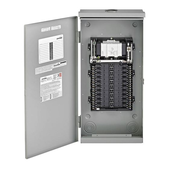
INSTALLATION INSTRUCTIONS
Outdoor Load Center Enclosure
Nos. LPxxx-3B, LPxxx-3L
IMPORTANT SAFETY INSTRUCTIONS - READ ALL INSTRUCTIONS BEFORE USING.
• TO AVOID FIRE, SHOCK OR DEATH: TURN OFF POWER SUPPLYING THIS EQUIPMENT, AND CONFIRM POWER IS OFF,
before installing, removing or servicing this equipment.
• This equipment MUST BE installed and serviced by an electrician.
• Replace all doors and covers before connecting power to this equipment.
• To be installed and/or used in accordance with electrical codes and regulations.
LIMITED PRODUCT WARRANTY
For Leviton's limited product warranty, go to www.leviton.com. For a printed copy of the warranty you may call 1-800-323-8920.
PATENTS PENDING
INSTALLATION
WARNING: TO AVOID FIRE, SHOCK OR DEATH: TURN OFF
POWER SUPPLYING THIS EQUIPMENT, AND CONFIRM
POWER IS OFF, before installing, removing or servicing
this equipment.
Step 1: Remove Load Center Door (Optional)
NOTE: The load center door can be removed for easier installation.
a. Lift door (A) upward to remove from hinge (B) (fig. 1).
b. When installation is complete, align the door hinge with the
hinge pin and insert downward until door is seated.
Step 2: Bottom feed applications (Optional)
NOTE: The Leviton
Load Center interior should be inverted for
®
bottom feed applications.
NOTE: Install the closing plate (included) to the overhead opening of
the enclosure for bottom feed applications.
NOTE: Before removing any knockouts from the enclosure, consult
the local electrical code to determine the knockout requirements.
a. Remove the mounting screws (C) and the green ground
bonding screw (D).
b. Invert the interior (E) and place into slots (F).
c. Replace the mounting screws (C) and green ground bonding
screw (D) to secure the interior (fig. 2). Torque all mounting
screws to 20 +/- 2 in-lbs.
d. To remove knockouts (G), first strike the center of the
knockout.
e. Pry each ring (H) up, one at a time, and grip both ends with a
pair of pliers.
f. Use the pliers to bend the rings (H) until they disconnect from
the enclosure (fig. 3).
Step 3: Enclosure Mounting
Surface or Semi-Flush Mounting
a. Remove deadfront (W) by loosening the securing screw (X) and
lifting the deadfront (W) off the enclsoure.
b. Remove mounting knockouts (I) from the back of the enclosure
(fig. 4).
c. Use outdoor approved screws or nails (not provided) in the
mounting knockouts (I) to secure the enclosure to the wall.
© 2018 Leviton Mfg. Co., Inc.
WARNING
Fig. 1
Door
(A)
Fig. 3
a.
Knockout
(G)
b.
Ring
(H)
c.
Ring
(H)
For Technical Assistance Call: 1-800-824-3005 (U.S.A. Only)
1 800 405-5320 (Canada Only) www.leviton.com
Fig. 2
Hinge
(B)
Hinge pin
Fig. 4
PK-A3230-10-00-0A
Interior (E)
inverted
Mounting screws
(x7)(C)
Green ground
bonding screw
(D)
Slot
(F)
Mounting
Knockouts
(I)
PK-A3230-10-00-0A
Advertisement
Table of Contents

Related Manuals for Leviton LP 3B Series


Summary of Contents for Leviton LP 3B Series
- Page 1 • Replace all doors and covers before connecting power to this equipment. • To be installed and/or used in accordance with electrical codes and regulations. LIMITED PRODUCT WARRANTY For Leviton’s limited product warranty, go to www.leviton.com. For a printed copy of the warranty you may call 1-800-323-8920. PATENTS PENDING INSTALLATION Fig.
- Page 2 Fig.8 to trim, near main breaker handle. Step 5: Branch Circuit Breakers WARNING: Leviton circuit breakers MUST BE used with a Leviton circuit breaker enclosure. a. Strip and connect the load phase (Q) and load neutral (R) wires to the load terminals (S) and ground wire to the ground Bonding strap bus (T) of the circuit breaker enclosure (fig.
Need help?
Do you have a question about the LP 3B Series and is the answer not in the manual?
Questions and answers