Table of Contents
Advertisement
Quick Links
Advertisement
Table of Contents

Related Manuals for Shaver HD-10


Summary of Contents for Shaver HD-10
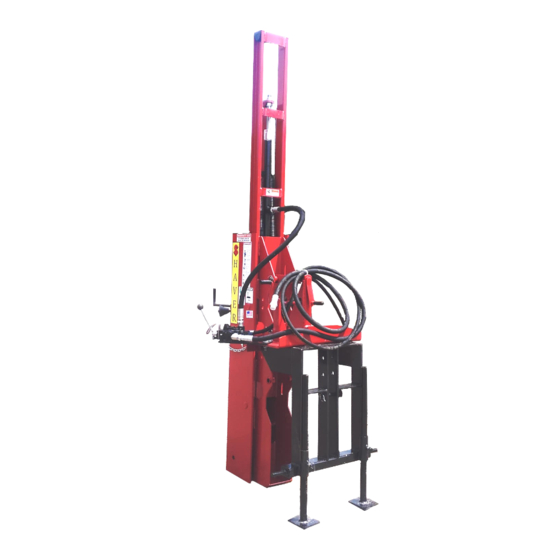
- Page 1 Operator’s Manual Hydraulic Post Driver Model HD-10 & HD-10-H Safety Operation Maintenance Repair Troubleshooting Parts Shaver Manufacturing Company 103 South Washington Avenue, Graettinger, Iowa 51342 Phone: (712) 859-3293 — Fax: (712) 859-3294 — www.shavermfg.com...
-
Page 2: Table Of Contents
Do not assemble, operate, or maintain the Shaver Post Driver until you read and Storage......29 understand the information contained in Service Procedures . -
Page 3: Safety Alert Symbols
Shaver Manufacturing Company cannot Safety Icon Nomenclature anticipate every possible circumstance that Read the manual might involve a potential hazard. The warnings in this supplement and on the product are, therefore, not all-inclusive. If a Eye protection method of operation not specifically... -
Page 4: Safety Warnings
Post Driver. . While transporting, instructions and warnings in this and all other never ride on or permit others to ride on the applicable manuals. Contact Shaver Post Driver. . Manufacturing Company. if any of the instructions provided are unclear or not Improper operating understood. -
Page 5: Hydraulic Hoses
WARNING WARNING Do not drop heavy objects on Potential pinch points. hoses. A sharp impact may cause Keep hands clear of Post internal damage to the hose. Driver while operating. Applying pressure to a damaged Never place hand(s) on hose may cause it to rupture, resulting in top of a post when inserting it into personal injury. -
Page 6: Introduction
Shaver the largest selling Post Driver in the country. The Shaver HD-10 (manual tilt adjustment) and HD-10-H (hydraulic tilt adjustment) Hydraulic Post Driver is a durable piece of equipment that, with regular maintenance, will provide many years of service. -
Page 7: Assembly Procedure
Assembly Procedure Recommended Tools The basic tools needed to assemble and maintain the HD-10 and HD-10-H Post Driver are shown below. Additional specialized tools may be required. HD-10 and HD-10-H Recommended Tools (continued) Description Heavy-Duty Retaining Strap Heavy-Duty Seal Picks... -
Page 8: Unpacking
10 ft (3.0 m) tall posts only - three-point valve carton, safety arm carton, and on model hitch or front tractor mount. HD-10-H, the tilt cylinder carton. The HD-10 and HD-10-H are shipped with the carriage channel bolts installed in the middle mounting position. WARNING... -
Page 9: Main Carriage Channel
Main Carriage Channel 2. Install appropriate short channel bracket (D1, D2) using bolts (D3) and lock washers 1. With road lock pin (B8) installed in lower (D4) (6 each). Tighten completely. hole of drive ram (A1), use a suitable overhead lifting device to raise (stand up) main carriage channel (B1). -
Page 10: Stabilizer Legs
Stabilizer Legs NOTE: If a different set of holes was used to mount channel bracket (D1 or D2), the height 1. Place three-point hitch weldment (K1) of the legs will need to be adjusted upside down on the floor. Install stabilizer accordingly. - Page 11 2. Install hydraulic base plate (F2) on three- 4. Install hydraulic cylinders (F3, F4) on point hitch weldment (K1), as shown. hydraulic base plate (F2), along with safety Install carriage bolts, washers, lever (F9, F10), as shown. Secure with lockwashers, and nuts removed in Step 1. Lynch pins (included).
- Page 12 d. Use a suitable floor jack to support the WARNING three-point hitch weldment. main carriage channel e. Loosen stabilizer leg lock bolts (K8), assembly is tall and heavy. and adjust floor jack up or down to avoid tip over, resulting in serious align base plate pivot pin hole with injury or death, leave the overhead short channel (D2) lower mounting...
-
Page 13: Hydraulic Valve
NOTE: If using manual base plate (E2) a. Remove the plugs from the hydraulic assembly, adjust forward tilt crank (E11) and control valve. Apply paste-type thread side tilt crank (E3) to align channel mounting sealant (T12) to pipe threads and pin holes. - Page 14 Ensure the oil is clean and properly filtered before connecting the Post Driver to a hydraulic power source. Failure to follow oil cleanliness standards voids the Shaver Post Driver warranty. (H1) Hydraulic Valve Control Lever Linkage. (G5) Control Valve Lever(s). (G10) Safety Lever Return Spring.
- Page 15 3. Attach the hydraulic hoses. b. Connect threaded fitting on pressure hose (1/2” x 120”) (G17) to control valve (G1 or H1) swivel fitting. c. Connect threaded fitting on return hose (1” x 120”) (G20) to control valve (G1 or H1) swivel fitting. (G15) Valve to Drive Ram Hose.
-
Page 16: Safety Stop Adjustment
Safety Stop Adjustment IMPORTANT NOTICE WARNING If the tilt cylinder hoses are attached differently than shown, the control of the drive ram will not To avoid serious injury, inspect the be as described in this manual. control valve safety stop before using the Post Driver the first time and/or before each daily use. -
Page 17: Rubber Debris Guard
3. To adjust the safety stop, do the following: Rubber Debris Guard a. Squeeze the control valve lever and the 1. Locate rubber debris guard (A4), guard control valve safety lever together to mounting strap bracket (A5), and bag expose the safety lever stop setscrew. containing hardware and caution tag (A6, A7, A8, and A9). -
Page 18: Safety Arm
Safety Arm 2. Attach safety arm frame (I2) to outside of short channel bracket (D1 or D2) with two WARNING 3/4-10 x 2” frame mounting bolts (I3) and self locking nuts (I4), as shown. Tighten nuts securely. To avoid serious injury or death, the safety arm must be installed after the Post Driver has been mounted on a machine, or the... - Page 19 4. Apply a light film of a good quality grease 6. Install the swing arm assembly. to the pivot shaft and attach roller bracket a. Apply a light film of a good quality (I6) to swing arm handle (I5) with roller grease to the pivot shaft on swing arm bracket nut (I9).
- Page 20 9. Install Lynch pin (I13) to secure the swing WARNING arm to the safety arm frame. To avoid serious injury or death, the safety arm must be installed after the Post Driver has been mounted on a machine, or the freestanding Post Driver has been secured to prevent tipping.
-
Page 21: Document Storage Tube
Document Storage Tube Post Driver Operation Operational Safety Tips 1. Follow all safety information contained in this manual and refer to safety decals located on the Post Driver. 2. Personal safety equipment must be worn at all times during operation, i.e. safety glasses, steel toe shoes, hearing protection, etc. -
Page 22: Operating Instructions
15. Do not operate the Post Driver with the NOTE: The HD-10 and HD-10-H Post Driver machine or power source unattended. will fit tractors with Category II or Category III The Post Driver requires two people for three-point hitches. Use bushings... -
Page 23: Preparing To Drive A Post
5. If traveling more than 100 feet to drive the 1. Loosen stabilizer leg lock bolts (K8) and first post, remove road lock pin (B8). Raise raise up each stabilizer leg (K7). Tighten drive ram (A1) and install the road lock pin the lock bolts to support the stabilizer legs. -
Page 24: Driving A Post
5. Lower Post Driver until drive ram (A1) firmly WARNING contacts the ground. 6. Continue to lower Post Driver main carriage To avoid personal injury or death, channel (B1) an additional 1” (2.5 cm). do not operate the Post Driver by This important step helps protect lower yourself. - Page 25 3. To drive the fence post straight, adjust the main carriage channel side-to-side and fore-and-aft using manual cranks (manual base plate) or second and third hydraulic control valve levers (hydraulic base plate). IMPORTANT NOTICE If the tilt cylinder hoses are attached differently than shown, the control of the drive ram will not be as described in this manual.
- Page 26 5. Close safety arm frame (I2) to secure the WARNING post (the adjustable roller assembly keeps tension on the post while it is being driven). Potential pinch points. Keep hands clear of Post Driver while operating. Never place hand(s) on top of a post when inserting it into the Post Driver.
-
Page 27: Dismounting Post Driver
7. Squeeze control valve safety lever (G7) and IMPORTANT NOTICE push control valve lever (G5) to release the drive ram and create impact. Posts will drive into the ground much straighter using shorter strokes. Use caution when driving small diameter wood and steel posts. Maximum impact is not necessary with these smaller diameter posts and can cause damage (splintering or breakage) of posts. - Page 28 3. Raise or lower the stabilizer legs to allow 5. Make sure all pressure is released drive ram I-beam full contact with the (zero pressure) from the Post Driver ground. Make sure the Post Driver is hydraulic system. Disconnect hydraulic stable.
-
Page 29: Troubleshooting
Refer to Service Information section pressure washer. assembly procedures for correct 2. Inspect the Shaver Post Driver. Replace orientation. any worn or damaged parts before using 3. Incorrect clearance between main carriage the Post Driver again. -
Page 30: Service Procedures
3. On hydraulic base plate Post Drivers, other applicable manuals. Contact Shaver tighten cylinder stop bolt (F11). Disconnect Manufacturing Company if any of the four tilt cylinder hoses (H5) from hydraulic... -
Page 31: Main Carriage Channel Disassembly
Main Carriage Channel 3. Connect retaining strap (T19) to both upper spring eyes, with the strap positioned Disassembly around the top of the drive ram lift yoke bar, as shown. NOTE: Be prepared to collect any hydraulic fluid that drains from the cylinder into a suitable container. - Page 32 5. Remove the retaining strap and the upper 9a. Slide the main carriage channel spring bracket. downward. 6. Remove upper cylinder rod self-locking nut 9b. Remove the springs from the bottom of (C4) and lock washer (C16) from drive the Post Driver between the drive ram and cylinder piston (C3).
-
Page 33: Drive Cylinder Seal Replacement
2. Be prepared to collect any hydraulic fluid that drains from the cylinder into a suitable IMPORTANT NOTICE container. Unscrew cylinder cap (C7) and remove cylinder piston rod (C3) from the Note the number and thickness of the shims, cylinder housing. and the location of each shim pack removed. - Page 34 4. Remove self-locking piston guide nut (C11) 7. Clean the seal groove in the cylinder cap and piston rod guide (C10), using a 1-1/4” and place the new seal in hot (120°F) water wrench to hold the piston rod guide while for ten minutes.
-
Page 35: Main Carriage Channel Assembly
11. Install piston guide (C10) and new Main Carriage Channel Assembly self-locking piston guide nut (C11), using 1. Install guide block shims (A3) and guide a 1-1/4” wrench to hold the piston guide blocks (A2) on the pins inside the drive ram while installing the piston guide nut. - Page 36 3. The main carriage channel should slide 7. If removed, install two rubber bumpers (B3) back and forth freely. on road lock bracket (B2). Install the road lock bracket on main carriage channel (B1) 4. With the drive ram assembly horizontal, with bolts (B6) and road lock bracket nuts check the up and down movement of the (B7).
- Page 37 9. Attach drive cylinder piston rod (C3) to the b. Use the retaining strap to pull (stretch) top of the drive ram I-beam using new lock the springs just enough to align holes washer (C16) and new self-locking nut in upper spring bracket and drive ram (C4).
-
Page 38: Forward And Side Tilt Cylinder
b. Completely tighten road lock bracket Forward and Side Tilt Cylinder nuts (B7) that were left loose in Step 7. Maintenance c. Completely tighten self-locking nuts (C12) that were left loose in Step 8. Cylinder Disassembly Tighten each nut slightly, in turn, to WARNING align the drive cylinder inside the main carriage channel. -
Page 39: Cylinder Assembly
5. Carefully clamp tilt cylinder (F3 or F4) 8. Use a sturdy seal pick to remove the seals mounting tube in a vise. Completely from the cylinder piston and discard. compress internal cylinder cap snap ring Clean and inspect the piston and replace if (F14) and pull cylinder rod assembly worn or damaged. - Page 40 4. Install new scraper seal (F25) in the 8. Lubricate cylinder tube (F21, F27) bore, cylinder piston groove, followed by O-ring piston (F19) seals, and cylinder cap (F15) seal (F26), and the second scraper seal seals. Install cylinder rod (F16, F17) (F25).
-
Page 41: Three-Point Hitch/Post Driver Assembly
11. Install tilt cylinder(s) (F3, F4) with Three-Point Hitch/Post Driver appropriate mounting pins (F7, F8, and/or Assembly D6) and secure with Lynch pins. Reconnect the hydraulic hoses. 1. With road lock pin (B8) installed in the lower hole of drive ram (A1), use a suitable overhead lifting device to raise (stand up) main carriage channel assembly (B1). -
Page 42: Service Parts
Service Parts... -
Page 48: Three-Point Hitch Assembly
Three-Point Hitch Assembly Safety Arm Assembly HD-10 Service Parts - Three-Point Hitch Assembly HD-10 Service Parts - Safety Arm Assembly Item No. Part No. Description Qty. Item No. Part No. Description Qty. MB-1201A-12 Upper Link Hitch Pin SM-0011-SAA Safety Arm Attachment... -
Page 49: Replacement Decals
Replacement Decals Document Storage Tube HD-10 Service Parts - Replacement Decals Item No. Part No. Description Qty. MS-165 Small SHAVER Decal MS-161 Large SHAVER Decal MS-169 Control Valve Decal MS-166 Safety Arm Decal MS-163 Pinch Area Warning Decal MS-181 Pinch Point Warning Decal... -
Page 50: Hydraulic Control Valves
Hydraulic Control Valves Single Control Lever Valve HD-10 Service Parts - Single Control Lever Valve HD-10 Service Parts - Single Control Lever Valve (continued) Item No. Part No. Description Qty. Item No. Part No. Description Qty. P-20 Control Valve (complete) -
Page 51: Triple Control Lever Valve
Triple Control Lever Valve HD-10-H Service Parts - Triple Control Lever Valve HD-10-H Service Parts - Triple Control Lever Valve (continued) Item No. Part No. Description Qty. Item No. Part No. Description Qty. P-23 Control Valve (complete) P-910183 O-Ring Swivel 90° Fitting —... -
Page 52: Drive Cylinder Assembly
Drive Cylinder Assembly HD-10 Service Parts - Drive Ram Cylinder Assembly Expanded View Of Safety Lever Assembly Item No. Part No. Description Qty. SM-1026 Drive Ram Cylinder (complete) SM-10261 Drive Ram Cylinder Tube SM-10266 Drive Ram Cylinder Piston Rod SM-10267... -
Page 53: Tilt Cylinder Assembly
Tilt Cylinder Assembly HD-10-H Service Parts - Fwd & Side Tilt Cylinder Assembly Item No. Part No. Description Qty. HBP-90812 Forward Tilt Cylinder HBP-90813 Side Tilt Cylinder HBP-908131 Tilt Cylinder Seal Kit, not shown HBP-908139 Snap Ring HBP-908136 Tilt Cylinder Cap/Gland... -
Page 54: Limited Warranty
RGA will be provided. This warranty shall not be interpreted to render Shaver liable for injury or damages of any kind or nature to person or property. This warranty does not extend to the loss of crops, loss because of delay in harvesting, or any expense or loss incurred for labor, substitute machinery, rental, or for any other reason. -
Page 55: Warranty Card
The Post Driver is shipped from the factory with a warranty card. If the card is lost or misplaced, please copy this page, fill in the information, and send it to Shaver Manufacturing Company. Warranty Card Please complete the warranty card and return to:... - Page 56 SHAVER HD-10 and HD-10-H Post Driver April 2009...