
Related Manuals for Johnson Controls Frick XL

Summary of Contents for Johnson Controls Frick XL
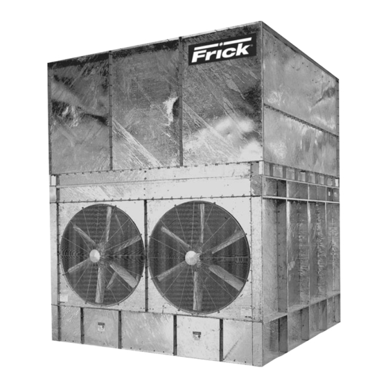
- Page 1 Form S140-600 IOM (NOV 2007) INSTALLATION - OPERATION - MAINTENANCE File: SERVICE MANUAL - Section 140 Replaces: S140-600/NOV 2005 Dist: 3, 3a, 3b, 3c EVAPORATIVE COOLING PRODUCTS...
-
Page 2: Table Of Contents
S140-600 IOM (NOV 07) XL EVAPORATIVE COOLING PRODUCTS Page 2 TABLE OF CONTENTS NOTE: Installation, operation, maintenance, and repair of this equipment should only be accomplished by qualifi ed person- nel. Failure to follow this note may result in improper installation and operation of the equipment and personal injury. Frick's XL Condensers are designed to ensure energy effi... -
Page 3: Preface
XL EVAPORATIVE COOLING PRODUCTS S140-600 IOM (NOV 07) GENERAL INFORMATION Page 3 PREFACE UNIT IDENTIFICATION This manual has been prepared to advise the owner and service personnel of recommended INSTALLATION, OPERATION, AND MAINTENANCE procedures recommended by Frick ® for XL Evaporative Cooling Equipment. Read the following instructions completely prior to installation. -
Page 4: Installation Tools
S140-600 IOM (NOV 07) XL EVAPORATIVE COOLING PRODUCTS Page 4 INSTALLATION adequate/loose fi eld wiring/connections. All personnel must Each beam should be sized in accordance with standard lock out and tag machinery before working on the condenser. engineering practices, 55% of the operating weight of the Proper safety precautions such as the use of insulating unit as a uniform load on the beam, allowing for a maximum soles/gloves and a trained “lookout buddy”... -
Page 5: Installation Instructions
XL EVAPORATIVE COOLING PRODUCTS S140-600 IOM (NOV 07) INSTALLATION Page 5 All units have 13/16 inch diameter mounting holes for mount- XLC CENTRIFUGAL FAN UNITS ing to the beams. The beams should be supported so that the XLC units are shipped in two pieces: the pan/coil section and unit is level. -
Page 6: Figure 4A. Mastic Placement For Blower Mounting
S140-600 IOM (NOV 07) XL EVAPORATIVE COOLING PRODUCTS Page 6 INSTALLATION The second step of installation is to mount the fan section to the pan/coil section as follows: 1. Remove guards from both ends and remove the vertical guard between the blowers to provide access to mounting holes. -
Page 7: Figure 6. Platform Layout
XL EVAPORATIVE COOLING PRODUCTS S140-600 IOM (NOV 07) INSTALLATION Page 7 FOUNDATION LAYOUT INFORMATION TABLE 2 FOR XLP UNITS XLP FOUNDATION LAYOUT DIMENSIONS Beams and/or piers should be sized in accordance with MODEL standard engineering practices, 55% of the operating S90 thru S175 weight as a uniform load. -
Page 8: Figure 7C. Xlp Coil Section Rigging
S140-600 IOM (NOV 07) XL EVAPORATIVE COOLING PRODUCTS Page 8 INSTALLATION Table 3 RIGGING CABLE LENGTHS Model Min. Cable Length 14 ft M - 2 Fan 13 ft M - 3 Fan 17 ft ML - 2 Fan 15 ft ML - 3 Fan 20 ft L - 2 Fan... -
Page 9: Optional Vibration Isolator Mounting Instructions
XL EVAPORATIVE COOLING PRODUCTS S140-600 IOM (NOV 07) INSTALLATION Page 9 OPTIONAL VIBRATION ISOLATOR MOUNTING INSTRUCTIONS Vibration isolators, purchased as an option, are used to minimize transfer of forces due to vibration/dynamic load- ing to or from unit. To install the isolator feet and rails, refer to Figure 9 and Figure 10 respectively and follow these instructions: ISOLATOR FEET... -
Page 10: Final Assembly Details
S140-600 IOM (NOV 07) XL EVAPORATIVE COOLING PRODUCTS Page 10 INSTALLATION Figure 10 - Vibration Isolator Rails FINAL ASSEMBLY DETAILS J. Check fans and pumps for correct rotation and electrical hook-up. 1. ELIMINATOR PLACEMENT K. See the Operation and Maintenance Manual for new belt Check the placement of the eliminator sections on the top run-in procedures. -
Page 11: Operating Instructions
XL EVAPORATIVE COOLING PRODUCTS S140-600 IOM (NOV 07) OPERATION Page 11 COLD WEATHER OPERATION OPERATION Frick Evaporative Condensers are suitable for most cold ® Frick Evaporative Condensers remove heat from the fl uid ® weather applications when supplied with proper capacity circulating in the coil by recirculating water over the outside of control and freeze protection. -
Page 12: Maintenance Instructions
S140-600 IOM (NOV 07) XL EVAPORATIVE COOLING PRODUCTS Page 12 MAINTENANCE chemical concentration of the water outside of the accept- MAINTENANCE able ranges listed above. Frick Evaporative Condensers accomplish condensing by ® • The unit interior including the condenser walls above evaporating water from the spray water system at the rate and below the coil, the coil and the sump basin should of two gallons per minute per one million BTU’s per hour of... -
Page 13: Figure 12. Xlc Spray Header Nozzle Orientation
XL EVAPORATIVE COOLING PRODUCTS S140-600 IOM (NOV 07) MAINTENANCE Page 13 pan water level should be even with the centerline of the competitive nozzles. There is adequate space below the overfl ow when the unit is not running. This will prevent the nozzle and a wide opening to allow large debris to be pulled pump from cavitating when the spray system is in operation. -
Page 14: Figure 14. Sheave Alignment
S140-600 IOM (NOV 07) XL EVAPORATIVE COOLING PRODUCTS Page 14 MAINTENANCE will promote belt wear and increase turnover. Groove gauges 3. Move the motor until there is enough slack in the belt so are also available to make it easy to see if the grooves are it can be removed without prying. -
Page 15: Fans
XL EVAPORATIVE COOLING PRODUCTS S140-600 IOM (NOV 07) MAINTENANCE Page 15 FANS valve should be installed in the pump discharge line and the pump fl ow rate adjusted to the correct water fl ow. The fans should be checked monthly for any debris caught 12. -
Page 16: Operation And Maintenance Schedule
S140-600 IOM (NOV 07) XL EVAPORATIVE COOLING PRODUCTS Page 16 MAINTENANCE OPERATION AND MAINTENANCE SCHEDULE EVERY 3 EVERY 6 TYPE OF SERVICE START-UP MONTHLY MONTHS MONTHS SHUTDOWN ANNUALLY Inspect General Condition of Unit Clean debris from unit Clean and fl ush sump Clean sump strainer Check and adjust sump water level Inspect heat transfer section... -
Page 17: Recommended Spare Parts
XL EVAPORATIVE COOLING PRODUCTS S140-600 IOM (NOV 07) MAINTENANCE Page 17 SPARE PARTS Frick recommends that the customer maintain the following spare parts “in stock” for the Evaporative Condenser. By maintaining ® this inventory of spare parts, continuous unit operation will be ensured. Contact your local Frick representative for pricing. - Page 18 S140-600 IOM (NOV 07) XL EVAPORATIVE COOLING PRODUCTS Page 18 NOTES...
- Page 19 XL EVAPORATIVE COOLING PRODUCTS S140-600 IOM (NOV 07) NOTES Page 19...
- Page 20 Take Control. ™ © 2007 Johnson Controls Inc. • • Subject to change without notice • Printed in USA • GUI 1M Supersedes: S140-600 IOM (1105) • Form S140-600 IOM (1107) ALL RIGHTS RESERVED www.frickcold.com...
Need help?
Do you have a question about the Frick XL and is the answer not in the manual?
Questions and answers