
Summary of Contents for D3 DesignCore RVP-TDA3 Series
- Page 1 DesignCore™ TDA3x Product Family Quick Start Guide Document No. 00C-131 Version 1.1 Release Date: 1/17/2019...
-
Page 2: Table Of Contents
D3Engineering.com ▪ 585.429.1550 www.d3engineering.com 585.429.1550 Table of Contents Introduction ..........................4 1.1 About the DesignCore™ RVP-TDA3x Development Kit for Advanced Driver Assistance Systems (ADAS) ..............................4 1.2 Use Cases Applicable to Each Kit ....................5 1.2.1 Kits Configured for Single-Camera Capture Display Use Cases and SurroundView Use Cases 1.2.2 Kits Configured for HDMI Capture and Display Use Case .......... - Page 3 Table 8. Full Menu Input Sequence for HDMI Capture Use Case ............... 32 Table 9. Common Problems and Possible Solutions ................... 33 © Copyright 2018. D3 Engineering. All rights reserved. DesignCore™ TDA3x Product Family ▪ Quick Start Guide Document No. 00C-131 ▪ Version 1.0 ▪ Release Date: 1/17/2019 - 3 - CONFIDENTIAL ▪...
-
Page 4: Introduction
D3Engineering.com ▪ 585.429.1550 www.d3engineering.com 585.429.1550 1.0 Introduction This Quick Start Guide applies to the following seven D3 Engineering kits: (The features specific to each kit are detailed later in this section.) • DesignCore™ RVP-TDA3x Development Kit for Advanced Driver Assistance Systems (ADAS) •... -
Page 5: Use Cases Applicable To Each Kit
D3Engineering.com ▪ 585.429.1550 www.d3engineering.com 585.429.1550 1.2 Use Cases Applicable to Each Kit (See Section 6.0 Running Your First Demo.) 1.2.1 Kits Configured for Single-Camera Capture Display Use Cases and SurroundView Use Cases • DesignCore™ RVP-TDA3x ADAS Development Kit • DesignCore™ RVP-TDA3x Development Kit •... -
Page 6: Images Of Modules For Each Kit
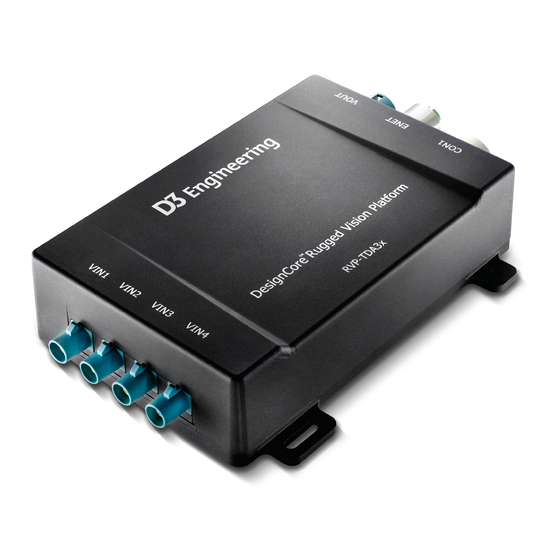
D3Engineering.com ▪ 585.429.1550 www.d3engineering.com 585.429.1550 1.4 Images of Modules for Each Kit Kit Name Overview Image of Kit Module DesignCore™ RVP-TDA3x ADAS Development Kit DesignCore™ RVP-TDA3x Development Kit DesignCore™ TDA3x Development Kit DesignCore™ TDA3x Automotive Starter Kit DesignCore™ TDA3x Product Family ▪ Quick Start Guide Document No. -
Page 7: Table 2. Kit Name And Overview Image Of Each Kit Module
D3Engineering.com ▪ 585.429.1550 www.d3engineering.com 585.429.1550 DesignCore™ DM50x Development Kit DesignCore™ DM50x Industrial Development Kit DesignCore™ DM50x Starter Kit Table 2. Kit Name and Overview Image of Each Kit Module DesignCore™ TDA3x Product Family ▪ Quick Start Guide Document No. 00C-131 ▪ Version 1.0 ▪ Release Date: 1/17/2019 - 7 - CONFIDENTIAL ▪... -
Page 8: Contents Of Rvp-Tda3X Adas Development Kit
Note: Contents in box may vary for other products in the TDA3x Product Family. Quantity D3 Part Number Description 1000391 Assembly, ADAS baseplate 1000396 Assembly, Wheel Chassis, ADAS 1000339 Assembly, Camera D3, ADAS 1000354 Screw, M5X16, Black 1000353 Nut, Stop, M5 1000320 Monitor 1000367 Cable, FAKRA Jack to FAKRA Jack, 11.5... -
Page 9: Images Of Key Parts In Rvp-Tda3X Adas Development Kit
D3Engineering.com ▪ 585.429.1550 www.d3engineering.com 585.429.1550 2.1 Images of Key Parts in RVP-TDA3x ADAS Development Kit Note: Some parts may already be assembled. 1000405 1000396 1000340 1000324 1000321 1000320 1000244 1000021 1000391 1000020 PCA-00C003056 1000367 Figure 1. Images of key parts in RVP-TDA3x ADAS Development Kit DesignCore™... -
Page 10: Getting To Know Your Rvp-Tda3X Adas Development Kit
D3Engineering.com ▪ 585.429.1550 www.d3engineering.com 585.429.1550 3.0 Getting to Know Your RVP-TDA3x ADAS Development Kit Below is a mechanical drawing of the system with labels. Figure 2. RVP-TDA3x ADAS Development Kit with parts labeled DesignCore™ TDA3x Product Family ▪ Quick Start Guide Document No. -
Page 11: Initial Setup
D3Engineering.com ▪ 585.429.1550 www.d3engineering.com 585.429.1550 4.0 Initial Setup 4.1 TDA3x and DM50x Document Applicable Kits: ISS Single-Camera Capture and Display Note: Images shown are of RVP-TDA3x. 1. Connect the TDA3x system to a computer to access the debug Serial console. Connect the provided USB-USB Micro B cable to the serial port, as shown below. - Page 12 D3Engineering.com ▪ 585.429.1550 www.d3engineering.com 585.429.1550 3. Next, connect the camera to the TDA3x system, as shown below. Camera connected to TDA3x module plugged into VIN4 4. Connect an HDMI cable that is attached to a display to the TDA3x system. HDMI Mini connected to the TDA3x system Note: HDMI OUT port is in a different...
-
Page 13: Rvp-Tda3X Adas Development Kit And Rvp-Dm50X Development Kit: Surroundview
D3Engineering.com ▪ 585.429.1550 www.d3engineering.com 585.429.1550 4.2 RVP-TDA3x ADAS Development Kit and RVP-DM50x Development Kit: SurroundView Note: Images shown are of RVP-TDA3x ADAS Development Kit. 1. To prepare the RVP-TDA3x ADAS Development Kit, first attach the two provided axle assemblies, 1000396. Screw them in to the main platform with the provided M5x14 bolts and M5 nuts. -
Page 14: Table 4. Joining The Cameras To The Vin Connections
D3Engineering.com ▪ 585.429.1550 www.d3engineering.com 585.429.1550 3. With the cameras mounted to the frame, use the provided cables to connect the cameras to the RVP-TDA3x. Table 5 (below) outlines the proper sequence for joining the cameras to the VIN connections. Connect four 1000339 cameras to RVP-TDA3x module. - Page 15 D3Engineering.com ▪ 585.429.1550 www.d3engineering.com 585.429.1550 4. To access most of the debugging and video interfaces for the RVP-TDA3x ADAS Development Kit, remove the Access Panel, which is marked on the RVP-TDA3x module, shown below. This panel is held in by two captive 4-40 screws. Access panel location on RVP- TDA3x module, showing captive 4- 40 bolts holding it in...
- Page 16 D3Engineering.com ▪ 585.429.1550 www.d3engineering.com 585.429.1550 7. The RVP-TDA3x ADAS Development Kit features a screen that mounts directly to the platform. Attach this screen to the kit platform as shown below and screw it in from the bottom. Display mount attached to the base of the ADAS Development Kit 8.
- Page 17 D3Engineering.com ▪ 585.429.1550 www.d3engineering.com 585.429.1550 9. Connect the display to the RVP-TDA3x system using the provided cable 1000285, HDMI- Mini HDMI. The full-size HDMI end of the cable plugs into the monitor, and the Mini HDMI end plugs into the RVP-TDA3x system. The monitor’s other cable is the power cable.
- Page 18 D3Engineering.com ▪ 585.429.1550 www.d3engineering.com 585.429.1550 10. Once the display is plugged in, power it on. The input should default to HDMI; with the system powered off, however, nothing should show up on the screen, and the monitor should be in a rest state (with red light on the monitor). Display powered on DesignCore™...
- Page 19 D3Engineering.com ▪ 585.429.1550 www.d3engineering.com 585.429.1550 11. Finally, connect the main power and Ethernet connectors to the RVP-TDA3x enclosure. The main connector provides power as well as breakouts for various busses. To get the system up and running, apply power. Use the other power supply provided with the ADAS Development Kit and the provided set of power cables to connect the RVP-TDA3x module to 12V DC, as shown below.
-
Page 20: Tda3X Automotive Starter Kit And Dm50X Starter Kit: Hdmi Capture And Display
D3Engineering.com ▪ 585.429.1550 www.d3engineering.com 585.429.1550 4.3 TDA3x Automotive Starter Kit and DM50x Starter Kit: HDMI Capture and Display Note: Images shown are of TDA3x Automotive Starter Kit. 1. Connect the TDA3x system to a computer to access the debug Serial console. Connect the provided USB-USB Micro B cable to the serial port, as shown below. - Page 21 D3Engineering.com ▪ 585.429.1550 www.d3engineering.com 585.429.1550 HDMI Mini connected to the TDA3x system HDMI OUT port 4. Connect an HDMI cable that is attached to a video source (for example, computer) to the TDA3x system in port labeled HDMI IN. HDMI Mini connected to the TDA3x system HDMI IN port 5.
-
Page 22: Configuring Your Pc
Depending on your Windows installation, the driver may install automatically. If it doesn’t, download the driver here: http://www.ftdichip.com/Drivers/CDM/CDM%20v2.10.00%20WHQL%20Certified.exe 2. Install terminal software a) D3 Engineering recommends Tera Term, downloadable here: http://logmett.com/tera-term-the-latest-version 3. Configure Serial Port a) Open Tera Term and select the Serial radio box, as shown in Figure 3 (below): Figure 3. -
Page 23: Linux
The Serial driver should already be installed and working. 2. Install Terminal Software a) D3 Engineering recommends Minicom, which is likely already installed on your PC. 3. Configure the Serial Port a) The RVP-TDA3x will enumerate with two serial ports; select the second option. -
Page 24: Using Gtkterm Rather Than Minicom
D3Engineering.com ▪ 585.429.1550 www.d3engineering.com 585.429.1550 5.2.1 Using GtkTerm Rather than Minicom 1. Use Aptitude to install GtkTerm from Terminal Note: Most modern Linux distributions such as Ubuntu include Aptitude as a default. a) Open Terminal and type: sudo apt-get update #Terminal command for updating Aptitude’s cached package list sudo apt-get install gtkterm #Terminal command for installing GtkTerm... -
Page 25: Figure 7. Sd Card Contents
D3Engineering.com ▪ 585.429.1550 www.d3engineering.com 585.429.1550 2. Verify that the SD Card comes preloaded with the needed binaries. If using your own SD Card, you’ll need the files listed below: Copy the BIOS binary file ‘AppImage’, located in ‘vision_sdk/binaries/apps/tda3xx_rvp_bios_all/vision_sdk/bin/tda3xx-rvp/sbl_boot/’ after successfully building VisionSDK, to the root of your SD Card. For SurroundView use cases, locate the TDA3x folder in ‘vision_sdk/apps/tools/surround_vision_tools/Srv_LUTs’... -
Page 26: Figure 8. Serial Console Output Menu
D3Engineering.com ▪ 585.429.1550 www.d3engineering.com 585.429.1550 3. Enable the Serial Console by following the instructions in 5.0 Configuring Your PC. Power on the TDA3x module by plugging in the power cable. Look for output on the Serial Console as it boots; see Figure 8 (below): Figure 8. - Page 27 D3Engineering.com ▪ 585.429.1550 www.d3engineering.com 585.429.1550 Figure 9. Capture settings menu 5. Running Use Cases With the image sensor chosen, start the desired use case — ISS Single Camera, SurroundView, or HDMI Capture — by navigating from the main menu, as outlined in the following pages.
-
Page 28: Iss Single Camera Capture Use Case
For a full menu input sequence for this use case, see Tables 5 and 6 (below). Note: D3 Engineering's rugged digital camera module was used for this example. Menu Input Selects Menu Option (runs with logo and stats overlays) -
Page 29: Surroundview Use Case With Calibration Steps
(See Table 4. Joining the Cameras to the VIN Connections.) Position the cameras to center the black squares inside each red rectangle. D3 Engineering recommends pointing the front camera a little higher from the ground and the rear camera a little lower to accommodate the 3D SurroundView use case’s... - Page 30 D3Engineering.com ▪ 585.429.1550 www.d3engineering.com 585.429.1550 Figure 11. Example of poor calibration and camera obstructions (above) illustrates poor calibration. Note that in the upper right Figure 11 camera, the red rectangles are not on the corners of the target, and many cables (obstructions) are visible.
-
Page 31: Table 7. Full Menu Input Sequence For Surroundview Use Case
D3Engineering.com ▪ 585.429.1550 www.d3engineering.com 585.429.1550 Note: D3 Engineering's rugged digital camera module was used for this example. nu Input Selects Menu Option (runs the 3D SurroundView demo) Character Systems Settings Capture Settings OV10640 DCM ISS Use-cases 3D SRV 4CH ISS capture + ISS ISP + DeWarp + Synthesis (DSP1) + Display Table 7. -
Page 32: Hdmi Capture Use Case
D3Engineering.com ▪ 585.429.1550 www.d3engineering.com 585.429.1550 6.3 HDMI Capture Use Case Note: Only the Starter Kits – TDA3 Automotive and DM50x – support the HDMI Capture UseCase. i. At main menu, press S to select System Settings. ii. Press 2 for Capture Settings. iii. -
Page 33: Troubleshooting
Verify that Terminal Setup (baud, flow control, etc.) configuration is correct as detailed in 5.0 Configuring Your PC. Table 9 (below) describes common problems and fixes for the TDA3x Product Family. For other problems or questions about the hardware, contact D3 Engineering. Problem Possible Solution(s) No Boot a) Verify that the Power Polarity is correct. -
Page 34: Reference Documentation
D3Engineering.com ▪ 585.429.1550 www.d3engineering.com 585.429.1550 8.0 Reference Documentation Document Location DesignCore™ RVP- Contact D3 Engineering. TDA3x Reference Design ▪ Technical Reference Manual Document Number: 00C010003 DesignCore™ RVP- Contact D3 Engineering. TDA3x Reference Design ▪ Design Overview Document Number: Texas Instruments...
Need help?
Do you have a question about the DesignCore RVP-TDA3 Series and is the answer not in the manual?
Questions and answers