Autel MaxiTPMS TS508 Manual
Hide thumbs
Also See for MaxiTPMS TS508:
- Manual (77 pages) ,
- Quick start manual (9 pages) ,
- Easy instructions (2 pages)
Table of Contents
Advertisement
Trademarks
®
Autel
,
MaxiSys
®
MaxiCheck
are trademarks of Autel Intelligent Technology Corp., Ltd., registered in
China, the United States and other countries. All other marks are trademarks or
registered trademarks of their respective holders.
Copyright Information
No part of this manual may be reproduced, stored in a retrieval system or transmitted, in
any form or by any means, electronic, mechanical, photocopying, recording, or
otherwise, without the prior written permission of Autel.
Disclaimer of Warranties and Limitation of Liabilities
All information, specifications and illustrations in this manual are based on the latest
information available at the time of printing.
Autel reserves the right to make changes at any time without notice. While information
of this manual has been carefully checked for accuracy, no guarantee is given to the
completeness and correctness of the contents, including but not limited to the product
specifications, functions, and illustrations.
Autel will not be liable for any direct damages or for any special, incidental, or indirect
damages or for any economic consequential damages (including lost profits).
IMPORTANT
Before operating or maintaining this unit, please read this manual carefully, paying extra
attention to the safety warnings and precautions.
For Services and Support:
http://pro.autel.com
www.autel.com
1-855-288-3587/1-855-AUTELUS (North America)
0086-755-86147779 (China)
Support@autel.com
For technical assistance in all other markets, please contact your local selling agent.
®
®
,
MaxiDAS
,
®
MaxiScan
,
MaxiRecorder
i
®
®
,
MaxiTPMS
,
and
Advertisement
Table of Contents

Related Manuals for Autel MaxiTPMS TS508


Summary of Contents for Autel MaxiTPMS TS508
- Page 1 Autel will not be liable for any direct damages or for any special, incidental, or indirect damages or for any economic consequential damages (including lost profits).
- Page 2 Safety Information For your own safety and the safety of others, and to prevent damage to the device and vehicles upon which it is used, it is important that the safety instructions herein presented throughout this manual be read and understood by all persons operating, or coming into contact with, the device.
- Page 3 Operate the vehicle in a well-ventilated work area: Exhaust gases are poisonous. Put blocks in front of the drive wheels and never leave the vehicle unattended while running tests. Use extreme caution when working around the ignition coil, distributor cap, ignition wires and spark plugs.
-
Page 4: Table Of Contents
Contents Using the Manual ....................1 ......................1 ONVENTIONS Bold Text ......................1 Terminology ......................1 Notes and Important Messages ................1 Hyperlinks ......................1 Illustrations ......................2 General Information ....................3 TPMS S ....................3 YSTEM EVIEW TPMS L .................... - Page 5 Erase Codes ....................... 27 Review Data ....................... 28 ......................29 UDIT EPORT TPMS Sensor Programming ................. 30 ......................31 REATE Program One by One ..................33 Program in One Operation ................... 35 ....................... 35 ANUAL REATE Program One by One ..................36 Program in One Operation ...................
-
Page 6: Using The Manual
Using the Manual This manual contains device usage instructions. Some illustrations shown in this manual may contain modules and optional equipment that are not included on your system. Contact your sales representative for availability of other modules and optional tools or accessories. Conventions The following conventions are used. -
Page 7: Illustrations
Illustrations Illustrations used in this manual are samples, the actual testing screen may vary for each vehicle being tested. Observe the menu titles and on-screen instructions to make correct option selection. -
Page 8: General Information
General Information TPMS System Review A tire pressure monitoring system (TPMS) is an electronic system designed to monitor the air pressure inside the pneumatic tires on various types of vehicles. TPMS report real-time tire-pressure information to the driver of the vehicle, either via a gauge, a pictogram display, or a simple low-pressure warning light. -
Page 9: Benefits Of Tpms
Benefits of TPMS The significant advantages of TPMS are summarized as follows: Fuel saving. Extended tire life. Decreased downtime and maintenance. Improved safety. Environmental efficiency. -
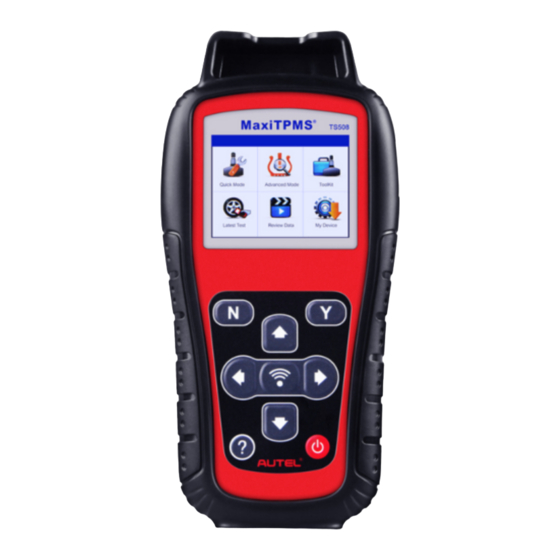
Page 10: Tool Information
Tool Information Functional Description Figure 3-1 TPMS TS508 SENSOR SLOT – Holds the MX-Sensor need to be programmed. LCD DISPLAY – Displays the menus and test screens. N BUTTON – Cancels a selection (or action) from a menu or return to previous menu. -
Page 11: Specifications
down to next screens for additional data. It is also used to view next trouble code when viewing DTCs. HELP BUTTON – Provides help information. POWER BUTTON – Long press the button to turn on/off the tool; or, short press the button to return to Home screen. -
Page 12: Icons
USB Cable Adapter – Allows online update, data printing, and power charging via PC connection or connect the device and power source with the Adapter Carry Case – A case to store the tool when not in use ... -
Page 13: Power Up By Dlc
Connect the device and the power source with the USB cable adapter. For optimum performance, always keep your tool sufficiently charged. It is recommended that you charge the tool for over 2 hours before the first use. NOTE Only use the USB cable adapter that is included in our pack to charge this tool. The use of un-approved power supplies may damage your tool and void the tool warranty. -
Page 14: To Enter The Setting Menu
Pressure Unit: Sets the pressure unit in kPa, Psi or Bar. Temperature Unit: Sets the temperature unit in degree Celsius or Fahrenheit. Beep Set: Turns on/off key-press beep. Distance Unit: Sets the distance unit in km or mile. Power-off: Sets the time to power off automatically. Date and Time: Allows setting date information of the tool. - Page 15 Figure 3-4 Sample Language Screen ID Format From System Setup screen, use the UP/DOWN scroll button to select ID Format, and press the Y button. From ID Format screen, use the LEFT/RIGHT scroll button to select the desired ID format. Figure 3-5 Sample ID Format Screen 3.
- Page 16 Figure 3-6 Sample Pressure Unit Screen Press the Y button to save your settings and return to previous menu, or press the N button to exit without change. Temperature Unit From System Setup screen, use the UP/DOWN scroll button to select Temperature Unit, and press the Y button.
- Page 17 Figure 3-8 Sample Beep Set Screen Press the Y button to save your selection or the N button to exit without change. Distance Unit From System Setup screen, use the UP/DOWN scroll button to select Distance Unit, and press the Y button. From Distance Unit screen, use the LEFT/RIGHT scroll button to select the desired unit of distance: km or mile.
- Page 18 Figure 3-10 Sample Auto Power-off Screen NOTE Before the tool powers off automatically, it will save all the TPMS test data. Next time when the tool is powered on, you may retrieve the recorded data or return to the last operation. When using external power, the scan tool stays on until you turn it off.
-
Page 19: Product Troubleshooting
press the Y button; wait for the About screen to appear. View tool information on screen. Press the N button to exit. Figure 3-12 Sample About Screen Product Troubleshooting This part describes problems that you may encounter while using the TPMS tool. Vehicle Linking Error A communication error occurs if the TPMS tool fails to communicate with the vehicle’s ECU (Electronic Control Unit) when running the diagnostic function. -
Page 20: Tpms Check & Diagnostics
TPMS Check & Diagnostics ® The MaxiTPMS TS508 is a new generation TPMS diagnostic & service tool specially designed to activate all known OEM/Universal TPMS sensors, and provide users with direct access to the vehicle’s ECU through OBD II connection, thus allowing users to reprogram sensor IDs and retrieve/clear TPMS DTCs, helping technicians to quickly find out faulty TPMS and turn off MILs. - Page 21 Figure 4-1 Sample Vehicle Type Screen Observe the menu title and use UP/DOWN scroll button to select by model and year to identify the vehicle being tested. TIPS The selected vehicle is remembered by the tool when a test is commenced. Select by Model Figure 4-2 Sample Select by Model Screen Select by Year...
- Page 22 Figure 4-4 Sample Select Tire Screen A function menu screen will show up (Figure 4-5). Use the UP/DOWN and LEFT/RIGHT scroll button to select a desired wheel and place the tool alongside the valve stem, point toward the sensor location and press the TEST button (Figure 4-6).
- Page 23 Figure 4-7 Sample Activated Sensor Information Screen This sensor information screen will appear for 3 seconds, then it will automatically turn to the next screen as below. Figure 4-8 Sample Sensor Activated Screen Wheel with a feedback icon, “√”, “X”, “D”, indicates wheel test has been finished. Refer to Table 4-1 for detailed description to learn what testing result each icon...
- Page 24 Table 4-1 Possible Results for Testing Icon Test Results Description √ Successful TPMS sensor is successfully activated and decoded. Sensor Read The tool displays the sensor information. Failed Sensor If the search period expires and no sensor is Read activated or decoded, it may be caused by wrong sensor fitting or non-functioning sensor.
- Page 25 Figure 4-9 Sample Magnet Activation Screen If the TPMS sensor requires tire deflation (of the order of 10PSI), then deflate the tire and place the tool alongside the stem while pressing the TEST button. Figure 4-10 Sample Deflation Activation Screen ...
-
Page 26: Select By Latest Test
Figure 4-12 Sample Tested Sensor Information Screen-1 Figure 4-13 Sample Tested Sensor Information Screen-2 [Pos] – Indicates the wheel sensor position. [ID-H/D] – Shows sensor ID data. [kPa/Psi/Bar] – Indicates tire pressure. [° C/° F] – Indicates tire temperature. [BAT] – Indicates battery condition. [Mode] –... - Page 27 An activation screen with the previously activated sensor information will show up (Figure 4-14). Use the UP/DOWN or LEFT/RIGHT scroll button to select the desired wheel, and press the TEST button to reactivate the sensor, or press the Y button to view all detailed sensor data (Figure 4-15).
-
Page 28: Tpms Relearn
TPMS Relearn This function, which provides users with quick access to the vehicle’s ECU, enables users to do TPMS diagnostics, such as reading/writing sensor IDs on vehicle ECU and reading/ clearing codes of TPMS system, and to save data for later reviews and printing. Connect the TPMS tool to the vehicle’s DLC with the OBD II cable. -
Page 29: Read Ids From Vehicle
Figure 4-19 Sample TPMS Diagnostic Screen The Relearn Procedure allows referring to the related procedures before performing Relearn. The Sensor Information enables retrieval of the OEM sensor maker, OEM frequency and OEM part number. Figure 4-20 Sample OEM Sensor Information Screen The OBD Location shows the OBD port on the vehicle being tested. -
Page 30: Write Ids To Vehicle
button to save data for future review, or the N button to exit without saving. Figure 4-21 Sample Read IDs from Vehicle Screen Write IDs to Vehicle From TPMS Diagnostic Menu, use the UP/DOWN scroll button to select the OBD II Relearn function to write IDs to vehicle directly without performing further procedures (Figure... -
Page 31: Read Codes
NOTE The OBD II Relearn function is not supported by all vehicles. If the OBD II Relearn item doesn’t present, that means the sensor’s ID of the vehicle you selected does not need to be written to the vehicle. The sensor writing procedure may vary for different vehicles being serviced. Please follow the onscreen instruction and take appropriate measures and selections to complete the process. -
Page 32: Erase Codes
Figure 4-25 Sample Read Codes Screen TIPS The saved DTC and sensor data can be reviewed in Review Data, which supports easy data playback and printing. Erase Codes From TPMS Diagnostic Menu, use the UP/DOWN scroll button to select Erase Codes, and press the Y button (Figure 4-19). -
Page 33: Review Data
Figure 4-27 Sample Erase Codes Complete Screen Review Data The Review Data function allows user to view and print out saved data of the latest TPMS diagnostic recordings by the service tool. Use the UP/DOWN and LEFT/RIGHT scroll button to select Review Data from Main Screen (Figure 3-2), and wait for the review data menu to appear. -
Page 34: Audit Report
NOTE Don’t use Delete All unless you are definitely sure what you are going to proceed. Audit Report After the user finished the TPMS test, the tool is capable of presenting all of its stored TPMS data in a HTML file when connected to a PC via an USB cable. The tool will automatically pop up an explorer window in PC screen when connected to an active USB port on the PC. -
Page 35: Tpms Sensor Programming
NOTE Programming function will only work with Autel’s MX-Sensor. Currently, there are two models available: Clamp-in Sensor and Snap-in Sensor, both with two types, one in orange color with 433MHz frequency, and one in dark gray color with 315MHz frequency. -
Page 36: Auto Create
Figure 5-2 Sample TPMS Status Screen Auto Create This function is designed to program the MX-Sensor by applying random IDs created according to the test vehicle, when it is unable to obtain the original sensor ID. Use the UP/DOWN scroll button and the LEFT/RIGHT scroll button to select TPMS from Main Menu (Figure 3-2), and press the Y button to confirm. - Page 37 Select by Model Figure 5-4 Sample Vehicle Model Screen Select by Year Figure 5-5 Sample Vehicle Year Screen For some vehicles (like Chrysler), an option screen will show up allowing users to choose between 4 Wheels test and 5 Wheels test mode before accessing the activation screen.
-
Page 38: Program One By One
Program One by One Use the UP/DOWN scroll button and LEFT/RIGHT scroll button to select MX-Sensor icon on the lower right corner of the function screen (Figure 5-1). NOTE The MX-Sensor icon on the lower right corner will not appear if the TPMS Sensor Programming is not supported by the selected vehicle. - Page 39 type of the inserted MX-sensor may be incorrect. Figure 5-9 Sample Programming Screen Figure 5-10 Sample Warning Screen After programming is finished, a series of beep sound will be heard and the tool will display the data details such as the sensor ID, the temperature and the battery voltage after testing the new programmed MX-Sensor.
-
Page 40: Program In One Operation
Figure 5-12 Sample Error Screen Press OK to return to the previous screen, and a sensor mark will appear on the right side of the screen, indicating the wheel sensor has been programmed. Figure 5-13 Sample Programmed Sensor Screen Program in One Operation Use the UP/DOWN scroll button to select MX-Sensor on the lower right corner. -
Page 41: Program One By One
Program One by One Follow the steps in Auto Create to select MX-Sensor icon and then select the required wheel and press the Y button. Use the UP/DOWN scroll button to select Manual Create and press the Y button. Figure 5-14 Sample Manual Create Screen Use the UP/DOWN scroll button and the LEFT/RIGHT scroll button to select the character and press the TEST button to confirm. -
Page 42: Program In One Operation
Figure 5-16 Sample Confirmation Screen Insert the correct MX-Sensor and press the Y button to start programming or the N button to exit. Program in One Operation Follow the steps in Auto Create to select MX-Sensor icon and then select Multiple Sensors and press the Y button. -
Page 43: Copy By Obd
Copy by OBD This function allows users to write in the saved sensor information to MX-Sensor after performing Read IDs from Vehicle in TPMS Diagnostic function. Program One by One Follow the steps in Auto Create to select MX-Sensor to enter the Programming function. -
Page 44: Copy By Activation
The select Multiple Sensors function to program up to 20 MX-Sensors in one operation. The TPMS tool will automatically generate sensor IDs based on the retrieved sensor ID. Select the IDs you want to program with. When the programming is completed, the newly programmed MX-Sensors should be relearned by the vehicle that the sensors to be mounted on. -
Page 45: Program In One Operation
Select Copy by Activation, insert the correct MX-Sensor into the sensor slot, and then press the Y button to start programming the retrieved sensor information to the MX-Sensor. Figure 5-22 Sample Copy by Acitivation Screen For program one by one, if you had successfully performed both the Read IDs from Vehicle function and the Activation function, the screen may show as below. - Page 46 Figure 5-24 Sample Get ID from Activation Screen When the programming is completed, the newly programmed MX-Sensors should be relearned by the vehicle that the sensors to be mounted on. NOTE For the vehicles not supported by Relearn function, please select the “Manual Create” option to enter the original sensor ID manually, or trigger the original sensor at the activation screen to get the sensor information, before programming the MX-Sensor.
-
Page 47: Rke & Rf Monitor
RKE & RF Monitor Today's keyless remotes -- also known as key fobs -- make life easier. But when your key fob stops working or starts to perform sporadically, it will be particularly frustrating. Check your key fob to make sure it is in top condition so it will work when you really need it. -
Page 48: Print And Update
Print and Update To print out retrieved data or update software, you will need the followings: TS508 tool PC or laptop with USB ports USB cable Print Data The Print Data function allows printing out TPMS DTC data recorded by the service tool by connecting the scan tool to a PC or laptop with the USB cable supplied. -
Page 49: Software Update
On the Sign In page, input your account ID and other information to log in, if you already have an account. If you are a new member to Autel and do not have an account yet, click the Create Autel ID button on the left side. - Page 50 Follow the update procedure to finish updating. Run Autel Update in the PC Suite program. Wait for the Log In window to pop up. Figure 7-2 Sample Log In Window Enter your Autel ID and password and wait for the Update window to display. If you forget your password unintentionally, you may always click the [Forget Password?] to link to our website and get your password back.
-
Page 51: View Or Delete Programs
the Status column of updated items. Anytime you could click the Pause button on the right side of screen to suspend all progresses, and the state of those suspended items would change to STOPPED. To resume updating process, you may need to select those suspended items again, and then click the Update Selected Items button. - Page 52 Figure 7-4 Sample Confirmation Window Click on Yes to delete the program(s) selected, or on No to cancel the action. The deleted program will automatically add to the end of program list in the UPDATE page in case you would like to install again. Theoretically, all programs of the latest versions will be automatically compatible with the older versions, but if your TPMS tool does have a problem of compatibility and need to retrieve the older version for some programs, please delete the new versions first...
-
Page 53: Compliance Information
Compliance Information FCC COMPLIANCE FCC ID: WQ82016-TS408 This device complies with Part 15 of the FCC Rules and with RSS-210 of Industry Canada. Operation is subject to the following two conditions: This device may not cause harmful interference. This device must accept any interference received, including interference that may cause undesired operation. - Page 54 7. Compliance Information FCC COMPLIANCE This device complies with Part 15 of the FCC Rules and with RSS-210 of Industry Canada. Operation is subject to the following two conditions: This device may not cause harmful interference. This device must accept any interference received, including interference that may cause undesired operation.
- Page 55 RoHS COMPLIANCE This device is declared to be in compliance with the European RoHS Directive 2011/65/EU. CE COMPLIANCE This product is declared to conform to the essential requirements of the following Directives and carries the CE mark accordingly: EMC Directive 2014/30/EU R&TTE Directive 199/5/EC Low Voltage Directive 2014/35/EU...
-
Page 56: Warranty And Service
Warranty and Service Limited One Year Warranty Autel warrants to its customers that this product will be free from all defects in materials and workmanship for a period of one (1) year from the date of the original purchase, subject to the following terms and conditions:...
Need help?
Do you have a question about the MaxiTPMS TS508 and is the answer not in the manual?
Questions and answers