
Subscribe to Our Youtube Channel
Related Manuals for GARO GNM3T-RS485


Summary of Contents for GARO GNM3T-RS485
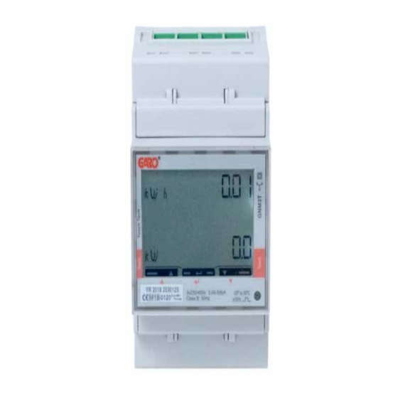
- Page 1 GARO GNM3T-RS485 as DLM meter DLM = Dynamic Loadbalancing Meter Installation and Programming Manual (EN) GARO AB Box 203, SE–335 25 Gnosjö info@garo.se garo.se...
-
Page 2: Table Of Contents
TABLE OF CONTENT IMPORTANT INFORMATION MODBUS CONNECTION Warnings ELECTRICAL CONNECTION POWER CABLES DLM METER SETTINGS Touch area System and CT Ratio settings System setting System options CT Ratio setting UT Ratio setting Confirm System, CT and UT Ratio settings Verify System, CT and UT Ratio settings Final confirmation of System, CT and UT Ratio settings Modbus settings Modbus address information... -
Page 3: Important Information
IMPORTANT INFORMATION Warnings All information in this guide is valid for GARO GNM3T-RS485 Make sure the electrical power is off before start of (GARO art nr 108740) installation process. Programming of GARO MID-certified energymeter GNM3T-RS485 consists of two parts. All electrical installation must be performed by an Part 1: System samt CT och UT Ratio settings. -
Page 4: Electrical Connection Power Cables
ELECTRICAL CONNECTION POWER CABLES N, 1, 2, 3: section 4 mm², torque 0.6 Nm 4-17: section 1.5 mm², torque 0.4 Nm... -
Page 5: Dlm Meter Settings
DLM METER SETTINGS Touch area System and CT Ratio settings Note: Can only be performed once This view is shown as startup view before the System and CT ratio settings are done. When the System and CT ratio settings are done, this view is not visible again. -
Page 6: System Setting
System setting 1P = 1phase + N 2P = 2phase + N (3-wire) 3P = 3phase (3-wire) 3Pn = 3phase + N (4-wire) System options 1. Click right touch area until wanted value is visible. 2. Press center touch area to confirm and ”no” is visible. 3. -
Page 7: Ct Ratio Setting
CT Ratio setting CT Ratio values (depending on the CT you use): 100/5A = CT Ratio 20 150/5A = CT Ratio 30 250/5A = CT Ratio 50 400/5A = CT Ratio 80 750/5A = CT Ratio 150 800/5A = CT Ratio 160 1250/5A = CT Ratio 250 1600/5A = CT Ratio 320 1. -
Page 8: Ut Ratio Setting
UT Ratio setting NOTE! Correct Ut Ratio value is”1” for 230/400V systems. 1. Press and hold center touch area until PrG is visible. 2. Click right touch area until wanted value is visible. Confirm by press center touch area and next figure starts to blink. Repeat until the complete value is correct and ”no”... -
Page 9: Confirm System, Ct And Ut Ratio Settings
Confirm System, CT and UT Ratio settings 1. Click right touch area to change to ”YES”. 2 Press center touch area to confirm the setting. Verify System, CT and UT Ratio settings The settings for System, CT and UT Ratio is visible step by step. Verify that all values are correct. When all settings are correct, go to step 7. -
Page 10: Final Confirmation Of System, Ct And Ut Ratio Settings
Final confirmation of System, CT and UT Ratio settings 1. Click right touch area to change to ”YES”. 2. Press center touch area to confirm. 3. System, CT and UT Ratio settings are now done. Main menu is visible. Modbus settings ”Longpress”... - Page 11 ”Longpress” both left and right touch area side to bypass the password. The blinking ”0” will stop to blink after 2 seconds. ”Longpress” center touch area until you see ”PASS”.
-
Page 12: Modbus Address Information
Modbus address information For a stand alone wallbox, recommended address is 002. This mode will paus the charging process if available current in the system is below 6A. 6A is the minimum av EV can charge according to standard. Note: No need to to do any settings in the wallbox webinterface. Modbus address 002 is the only adress that you can use if you do not have any Wifi-module installed in your wallbox Modbus address 002 is only valid for stand alone wallbox... -
Page 13: Set The Modbus Adress
Set the Modbus Adress 1. Longpress center touch area. 00”1” starts to blink. 2. Click left or right touch area to modify the figure. 3. Longpress center touch area to change to next figure and repeat step 2. 4. When the adress is correct, longpress center touch area to confirm the address. -
Page 14: Set/Verify The Baudrate
Set/verify the Baudrate NOTE! Correct Value:Baudrate: 9.6 1. Click left touch area until ”bAud” is visible. Default is 9.6 and this is correct. If you need to change bAud, longpress center touch area and click left or right touch area until 9.6 is visible. Confirm by longpress center touch area. -
Page 15: Confirm Settings
Confirm settings 1. Click left touch area until ”End” is visible. 2. Longpress center touch area when ”End” is visible and the setting is confirmed. 3. The square is blinking when DLM meter have communication with the wallbox.
Need help?
Do you have a question about the GNM3T-RS485 and is the answer not in the manual?
Questions and answers