
Related Manuals for GARO GNM3T-LP RS485 N


Summary of Contents for GARO GNM3T-LP RS485 N
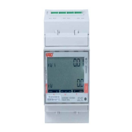
- Page 1 GARO GNM3T-LP RS485 N as DLM meter DLM = Dynamic Loadbalancing Meter Installation and Programming Manual (EN) GARO AB Box 203, SE–335 25 Gnosjö info@garo.se garo.se...
-
Page 2: Table Of Contents
TABLE OF CONTENT INFORMATION MODBUS CONNECTION Warnings ELECTRICAL CONNECTION POWER CABLES DLM METER SETTINGS Touch area System setting CT Ratio setting UT Ratio setting Modbus address information Set the Modbus Adress Set/verify the Baudrate Set/verify the Parity and stopbit Confirm settings... -
Page 3: Information
INFORMATION Warnings All information in this guide is valid for GNM3T-LP RS485 N Make sure the electrical power is off before start of (GARO art nr 109385) installation process. All electrical installation must be performed by an auhorized electrician. MODBUS CONNECTION Install the DLM meter in the mains cabinet you want to monitor. -
Page 4: Electrical Connection Power Cables
ELECTRICAL CONNECTION POWER CABLES N, 1, 2, 3: section 4 mm², torque 0.6 Nm 4-17: section 1.5 mm², torque 0.4 Nm... -
Page 5: Dlm Meter Settings
DLM METER SETTINGS Touch area ”Longpress” center touch area until you see ”PASS”. -
Page 6: System Setting
”Longpress” both left and right touch area to bypass the password. The blinking ”0” will stop to blink after 2 seconds System setting 1P = 1phase + N 2P = 2phase + N (3-wire) 3P = 3phase (3-wire) 3Pn = 3phase + N (4-wire) 1. -
Page 7: Ct Ratio Setting
CT Ratio setting CT Ratio values (depending on the CT you use): 100/5A = CT Ratio 20 150/5A = CT Ratio 30 250/5A = CT Ratio 50 400/5A = CT Ratio 80 750/5A = CT Ratio 150 800/5A = CT Ratio 160 1250/5A = CT Ratio 250 1600/5A = CT Ratio 320 1. -
Page 8: Ut Ratio Setting
UT Ratio setting NOTE! Correct Ut Ratio value is ”1” for 230/400V systems. 1. Click left touch area until ”Ut rAtIo” is visible. If you need to change the Ut Ratio value, follow below instructions: 2. Longpress center touch area and PrG is visible. 3. -
Page 9: Modbus Address Information
Modbus address information For a stand alone wallbox, recommended address is 002. This mode will paus the charging process if available current in the system is below 6A. 6A is the minimum av EV can charge according to standard. Note: No need to to do any settings in the wallbox webinterface. Modbus address 002 is the only adress that you can use if you dont have any Wifi-module installed in your wallbox Modbus address 002 is only valid for stand alone wallbox... -
Page 10: Set The Modbus Adress
Set the Modbus Adress 1. Longpress center touch area. 00”1” starts to blink. 2. Click left or right touch area to modify the figure. 3. Longpress center touch area to change to next figure and repeat step 2. 4. When the adress is correct, longpress center touch area to confirm the address. -
Page 11: Set/Verify The Baudrate
Set/verify the Baudrate NOTE! Correct Value:Baudrate: 9.6 Click left touch area until ”bAud” is visible. Default is 9.6 and this is correct. If you need to change baud, longpress center touch area and click left or right touch area until 9.6 is visible. Confirm by longpress center touch area. -
Page 12: Confirm Settings
Confirm settings 1. Click left touch area until ”End” is visible. 2. Longpress center touch area when ”End” is visible and the setting is confirmed. 3. The square is blinking when DLM meter have communication with the wallbox.