
Subscribe to Our Youtube Channel
Related Manuals for GARO GNM1D-RS485


Summary of Contents for GARO GNM1D-RS485
- Page 1 GARO GNM1D-RS485 as DLM meter DLM = Dynamic Loadbalancing Meter Installation and Programming Manual (EN) GARO AB Box 203, SE–335 25 Gnosjö info@garo.se garo.se...
-
Page 2: Table Of Contents
TABLE OF CONTENT INFORMATION MODBUS CONNECTION Warnings ELECTRICAL CONNECTION POWER CABLES DLM METER SETTINGS Touch area Modbus address information Set the Modbus Address Set/varify the Baudrate setting Set/varify the Parity and stopbit Final step... -
Page 3: Information
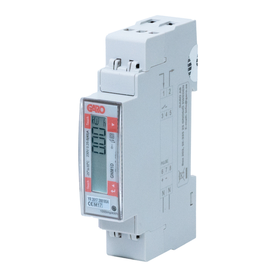
INFORMATION Warnings GARO GNM1D-RS485 (GARO art nr 108044) Make sure the electrical power is off before start of installation process. All electrical installation must be performed by an auhorized electrician. MODBUS CONNECTION Install the DLM meter in the mains cabinet you want to monitor. -
Page 4: Electrical Connection Power Cables
ELECTRICAL CONNECTION POWER CABLES N 1 2 F=Fuse 315mA if required by local regulation 1, 2, N: section 2.5-16 mm², torque 1.1 Nm 3-8: section 1.5 mm², torque 0.4 Nm DLM METER SETTINGS Touch area... - Page 5 Press lower touch area 3 seconds and ”PASS” is visible for 2 seconds before ”0000” is visible. Press lower and upper touch area 2 seconds tobypass the password.
-
Page 6: Modbus Address Information
Click upper touch area until you see ”AddrESS” Modbus address information For a stand alone 1-phase wallbox, recommended address is 002. This mode will paus the charging process if available current in the system is below 6A. 6A is the minimum av EV can charge according to standard. -
Page 7: Set The Modbus Address
Set the Modbus Address 1. Press lower touch area 3 seconds and ”current Modbus Address is visible. 2. Click upper or lower touch area to modify the blinking figure. 3. Press lower touch area 2 seconds to change to next figure. Repeat step 2 and 3 until the wanted adress is visible. 4. -
Page 8: Set/Varify The Baudrate Setting
Set/varify the Baudrate setting 1. Click upper touch area until ”bAud” is visible. Default is 9.6 and this is correct. 2. Press lower touch area 2 seconds and current Baudrate is visible. 3. Click upper or lower touch area until 9.6 is visible. 4. -
Page 9: Final Step
3. Press lower touch area 2 seconds to confirm and current stopbit setting is visible. 4. Press lower touch area 2 seconds and stopbit value is visible. Correct value is ”1”. Click upper touch area to change the value if needed.
Need help?
Do you have a question about the GNM1D-RS485 and is the answer not in the manual?
Questions and answers
Jag har en mätare med beteckning GNM1D. Hur nollställer man rESET? Nollställning av alla räkneverk för förbrukningsmätning?