Advertisement
A
VIEW IR S
UTO
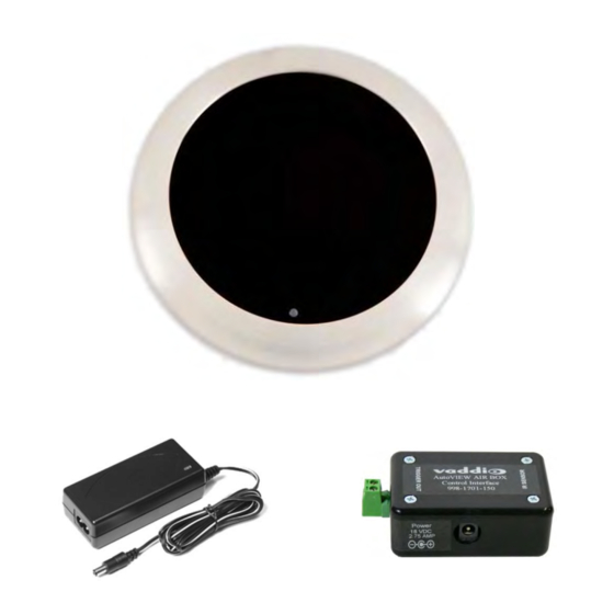
Single Ceiling Mounted Active IR Sensor with AutoVIEW IR
Control Interface and Power Supply
P/N:
999-1701-100 North America
999-1701-101 International
©2012 Vaddio - All Rights Reserved ● AutoVIEW IR Sensor Kit ● Document Number 341-233-1 Rev. C
K
ENSOR
I
NSTALLATION AND
IT
U
G
SER
UIDE
Advertisement
Table of Contents

Related Manuals for VADDIO 999-1701-100


Summary of Contents for VADDIO 999-1701-100
- Page 1 VIEW IR S ENSOR Single Ceiling Mounted Active IR Sensor with AutoVIEW IR Control Interface and Power Supply P/N: 999-1701-100 North America 999-1701-101 International ©2012 Vaddio - All Rights Reserved ● AutoVIEW IR Sensor Kit ● Document Number 341-233-1 Rev. C...
- Page 2 AutoVIEW IR Sensor Kit Inside Front Cover - Blank AutoVIEW IR Sensor Kit Manual 341-233-1 Rev. C Page 2 of 8...
- Page 3 Read and understand all instructions before using. Do not operate any device if it has been dropped or damaged. In this case, a Vaddio technician must examine the product before operating. To reduce the risk of electric shock, do not immerse in water or other liquids and avoid extremely humid conditions.
- Page 4 One (1) Power Cord (International version ships with UK and Euro power cables) Installation: Installation of the AutoVIEW IR Presenter Camera Control System is as unique as it is simple. With any Vaddio product, understanding the key system components is essential.
- Page 5 The AutoVIEW IR (AIR Box) Control interface supplies power the IR Senor and returns a closure pair (short to ground) to the TRIGGER OUT which can be connected into any Vaddio or other device with a trigger input. The plastic box for the control interface is approximately 3” (76.2mm) W x 2” (50.8mm) H x 1” (25.4mm) D and...
- Page 6 AutoVIEW IR Sensor Kit Basic Installation The AutoVIEW IR Sensor is a modified Optex Sensor usually used in automatic door systems. 1) Affix the mounting template to the sensor mounting position 2) Drill or cut a 5-1/8” (130mm) round mounting hole for the sensor Recommended distance to the nearest wall is 11”...
- Page 7 Vaddio Customer Service: Vaddio will test, repair, or replace the product or products without charge if the unit is under warranty and is found to be defective. If the product is out of warranty, Vaddio will test then repair the product or products. The cost of parts and labor charge will be estimated by a technician and confirmed by the customer prior to repair.
- Page 8 Toll Free: 800-572-2011 ▪ Phone: 763-971-4400 ▪ FAX: 763-971-4464 www.vaddio.com ©2010 Vaddio - All Rights Reserved. Reproduction in whole or in part without written permission is prohibited. Specifications and pricing are AutoVIEW IR Sensor Kit Manual 341-233-1 Rev. C Page 8 of 8 subject to change without notice.
Need help?
Do you have a question about the 999-1701-100 and is the answer not in the manual?
Questions and answers