
Subscribe to Our Youtube Channel
Related Manuals for Solid State Logic SSL SDI


Summary of Contents for Solid State Logic SSL SDI
- Page 1 www.solidstatelogic.com Network I/O – SDI SDI to Routable Audio Network and/or MADI User Guide Network I/O SDI. This is SSL.
- Page 2 Dante™ and Audinate™ are registered trademarks of Audinate Pty Ltd Document History September 2014 – Initial Release 1.0 Page B SDI – User Guide...
-
Page 3: Table Of Contents
Table of Contents Introduction Introduction Key Features Full Broadcast Specification Front Panel Layout Front Panel Indicators Usage Cases Network I/O – SDI to Dante Infrastructure Network I/O – SDI to MADI Infrastructure Hardware Connectivity Power Network (Dante) MADI Sync (PHD I/O) Block Diagrams SDI Block Diagram Audio Matrix Diagram... - Page 4 Other settings Network Sample Rate Synchronization Word/Video Sync Termination MADI Dante Optional Module (MADI SFP Fibre) Card Configuration System Delay Alive Time Hardware Configuration Dante Controller Basic Settings Network Config Key things to help you with IP addressing: Appendices Appendix A – Specifications Appendix B –...
-
Page 5: Introduction
Full Broadcast Specification (Option) Redundant Two x SFP MADI PSU Inputs Modules 7&8 5&6 3&4 1&2 Solid State Logic 100-240 VAC, 50/60 Hz Max 90 VA Fuse T1AH/250VAC AES/EBU I/O 1-4 MADI Optical I/O WC/VBB AES11 in Net 1 Net 2... -
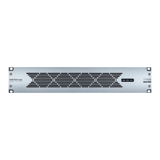
Page 6: Front Panel Layout
Front Panel Layout Front Panel Indicators Green – Normal operation STATUS Green – Normal operation STATUS Off – Normal operation – See SDI Manager software for fault details Page 2 SDI – User Guide... -
Page 7: Usage Cases
Usage Cases SDI can be used in a variety of scenarios: I/O – SDI eTwOrK ANTe NFrASTrUCTUre Dante Console MADI Console Dante wireless Mic receiver MADI Bridge Primary Network Switch Secondary Network Switch Dante Intercom 1 to 8 Connection 8 Inputs 8 Outputs 1 to 8 •... -
Page 8: Hardware Connectivity
Hardware Connectivity Ower Solid State Logic Network I/O – SDI includes redundant PSU with IEC connectors, either supply can 100-240 VAC, 50/60 Hz individually power the unit – both should be used for redundancy. Ideally these should Max 90 VA Fuse T1AH/250VAC be connected to separate mains supplies to provide external connection redundancy. -
Page 9: Block Diagrams
Block Diagrams SDI B LOCK IAGrAM Delay Audio Audio Extract Pass Extractor Buffer Drop Audio Drop Embedder Rx SRC enable Gp1 to Gp4 Audio (Setting per group) Embedder Router Enable Audio In Audio Buffer Use SRC Audio Out Audio Alignment Clock Tx Embedder Buffer... - Page 10 Intentionally blank page Page 6 SDI – User Guide...
-
Page 11: Connecting A Pc
Connecting a PC eTwOrK Configuration of the SDI unit is carried out using the ‘SDI Manager’ PC application. This programme can be downloaded from SSL’s website here. Net 1 Net 2 Connect a Windows™ PC to the Net 1 connector on the SDI unit using a standard network cable. - Page 12 IP Address Continued... Having checked you can connect to the device, now close the connection by right-clicking and selecting Close. The IP settings cannot be altered whilst the unit is active. Right-click on the target device and select Change Network Settings... This will allow you to set the SDI unit into DHCP mode or to select a fixed address to suit your requirements.
-
Page 13: Software Features
Software Features The Network I/O – SDI Manager software window is divided into four panes: • Device Selection shows available units and their connection status • Crosspoint Status shows current connections and the buttons for file access • Crosspoint Control is used to create or remove connections •... -
Page 14: Device Configuration Files
Device Configuration Files Device configurations can also be stored using the Load and Save buttons in the centre pane – these files are stored as .cfg (configuration) files. For further details, see Other Settings on page 11. The example shown contains three crosspoint routing files and one device configuration file. -
Page 15: Other Settings
Routes are connected by highlighting sources and destinations in their respective columns and clicking The selected routes will now be added to the existing routes shown in the crosspoint status window. can also be used in this pane of the software to remove routes based on the destination(s) selected. -
Page 16: Sample Rate
Sample rate ➭ General Sample Rate – Set the general sample rate for the SDI unit to match the wider environment. ➭ Sample Rate Adaptation Source allows the unit’s sample rate to be automatically adjusted as an external device changes. The adaption source can be set to any of the separate or embedded clock reference signals. -
Page 17: Phd
For future use. Dante It is recommended that these settings are managed using the Dante controller application only and not via SDI Manager. The information relating to the interface is included for clarity. See page16 for information relating to Dante Controller. Optional Module (MADI SFP Fibre) Each of the SFP fibre MADI interfaces, SFP 1 and SFP 2, has its own settings pane. -
Page 18: Card Configuration
Card Configuration This settings tab provides the configuration control for each of the four, 2-channel SDI interface cards. The left window is used to select the interface pairs and changes are made in the value column of the right window. Double-click in the appropriate field to alter settings. -
Page 19: Hardware Configuration
Hardware Configuration This tab provides rack hardware and software version details. It is for information only and no settings are available. SDI – User Guide Page 15... -
Page 20: Dante Controller Basic Settings
Dante Controller Basic Settings When using SDI with a Dante network all the Dante and other network settings should be set from Audinate’s Dante Controller software (downloadable for OSX and Windows here: Dante Controller). Detailed instruction for this software can be found in the Dante Controller Manual –... -
Page 21: Appendices
Appendices A – S PPeNDIx PeCIFICATIONS Parameter value Notes Depth 366mm ( 14.5") Height 89mm ( 3.5") 2 RU Width 438mm ( 17.25") Excluding rack ears Width 482mm ( 19") Including rack ears Weight 6.1kg ( 13.4 lb) Power < 90 VA Boxed size 500 x 500 x 160mm ( 19 x 19 x 6.3") Boxed weight... -
Page 22: Appendix C - Connector Pinouts
C – C PPeNDIx ONNeCTOr INOUTS AeS/eBU Inputs/Outputs (1–8, 9–16) Location: Rear Panel Connector Type: 25-way D-type female Description Notes: Out channels 7/8 Outputs Out channels 7/8 Ground Out channels 5/6 Out channels 5/6 Ground Out channels 3/4 Out channels 3/4 Ground Out channels 1/2 Out channels 1/2... -
Page 23: Appendix D - Safety Notices
D – S PPeNDIx AFeTy OTICeS General Safety • Please read and keep this document. • Adhere to all warnings and follow instructions. • This Electrical equipment should not be used near water. • Cleaning should only be with dry cloths or products compatible with electrical devices – never when the unit is powered. -
Page 24: For Eu
Solid State Logic has conformed and this product has conformed to European Union’s Directive 2011/65/EU on Restrictions of Hazardous Substances (RoHS) as well as the following sections of California law which refer to RoHS, namely sections 25214.10, 25214.10.2, and 58012, Health and Safety Code;... -
Page 25: Notes
OTeS SDI – User Guide Page 21... - Page 26 No part of this publication may be reproduced in any form or by any means, whether mechanical or electronic, without the written permission of Solid State Logic, Oxford, OX5 1RU, England As research and development is a continual process, Solid State Logic reserves the right to change the features and specifications described herein without notice or obligation.
Need help?
Do you have a question about the SSL SDI and is the answer not in the manual?
Questions and answers