Advertisement
TF4
Digital Timer
INSTRUCTION MANUAL
Thank you for purchasing Hanyoung Nux products.
Please read the instruction manual
carefully before using this product, and use the product correctly.
Also, please keep this instruction manual where you can see it any time.
▍ Safety information
Please read the safety information carefully then use the product correctly.
The alerts declared in the manual are classified into Danger, Warning and Caution according to their importance
DANGER
Indicates an imminently hazardous situation which, if not avoided, will result in death or serious injury
WARNING Indicates a potentially hazardous situation which, if not avoided, could result in death or serious injury
CAUTION
Indicates a potentially hazardous situation which, if not avoided, may result in minor injury or property damage
DANGER
• The input/output terminals are subject to electric
shock risk. Never let the input/output terminals come
in contact with your body or conductive substances.
WARNING
• Any use of the product other than those ecified by the
manufacturer may result in personal injury or property
damage.
• If there is a possibility that a malfunction or abnormality
of this product may lead to a serious accident to the system,
install an appropriate protection circuit on the outside.
• Since this product is not equipped with a power switch
and fuse, install them separately on the outside.
(fuse rating: 250 VAC 0.5 A).
• Please supply the rated power voltage, in order to
prevent product breakdowns or malfunctions.
• To prevent electric shocks and malfunctions, do not
supply the power until the wiring is completed.
• The product does not have an explosion-proof structure,
so avoid using it in places with flammable or explosive
gases.
• Never disassemble, modify, process, improve or repair
this product, as it may cause abnormal operations,
electric shocks or fires.
1s
• Please disassemble the product after turning OFF the
power. Failure to do so may result in electric shocks,
product abnormal operations or malfunctions.
0.1s
• Please use this product after installing it to a panel,
because there is a risk of electric shock.
▍ Suffix code
Model
Code
TF4-
□
□
□
□
A
Time
B
specification
C
U
Display
D
A
Input voltage
D
R
Control output
T
▍ Specification
Power voltage
Voltage fluctuation rate
Power consumption
Reset
Inhibit
External reset or Inhibit : Minimum input signal width 0.02 s
Contect output
Control
output
Contectless output
Repetition of operating time
Setup error
Effect of voltage
Effect of temperature
Installation method
Operating method
Operation Mode
Reset method
External connection method
Contect output
Input signal
method
Contectless output
Relay
Control
output
Transistor
Display
7 Segment LED (Character Height: 11 ㎜ , Character Width: 8 ㎜)
Up display
Processing
direction of digit
Down display
Decimal system
Sexagesimal system
Insulation resistance
(Based on 500Vd.c. mega Part of conduction terminal and exposured non-electrified metal part)
2000Va.c. 50/60 Hz for 1 minute (Electric conduction part and disclosed non-electrically
Dielectric strength
Noise immunity
Square-wave by noise simulator ±2 KV (between operational power terminals)
Destruction
10 - 55 Hz (for 1 minute) single amplitude 0.75 ㎜ X · Y · Z each direction, 2h
Vibration
Malfunction
10 - 55 Hz (for 1 minute) single amplitude 0.5 ㎜ X · Y · Z each direction, 2h
Destruction
Shock
Malfunction
Mechanical
Relay
life time
Electrical
Ambient temperature &humidity
Storage temperature
Weight(g)
HANYOUNGNUXCO.,LTD
28, Gilpa-ro 71beon-gil,
Michuhol-gu, Incheon, Korea
TEL : +82-32-876-4697
http://www.hynux.com
CAUTION
• The contents of this manual may be changed without prior notification.
• Please make sure that the product specifications are the same as you ordered.
• Please make sure that there are no damages or product abnormalities occurred during shipment.
• Please use the product in places where corrosive gases (especially harmful gases,
ammonia, etc.) and flammable gases are not generated.
• Please use the product in places where vibrations and impacts are not applied directly.
• Please use the product in places without liquids, oils, chemicals, steam, dust, salt, iron, etc.
• Please do not wipe the product with organic solvents such as alcohol, benzene, etc.
(use neutral detergents).
• Please avoid places where large inductive interference, static electricity, magnetic
noise are generated.
• Please avoid places with heat accumulation caused by direct sunlight, radiations, etc.
• Please use the product in places with elevation below 2000 m.
• When water enters, short circuit or fire may occur, so please inspect the product
carefully.
• When there is a lot of noise from the power, we recommend to use insulation transformer
and noise filter. Please install the noise filter to a grounded panel, etc. and make the
wiring of noise filter output and power supply terminal as short as possible.
• Tightly twisting the power cables is effective against noise.
• Do not wire anything to unused terminals.
• Please wire correctly, after checking the polarity of the terminals.
• When you install this product to a panel, please use switches or circuit
breakers compliant with IEC60947-1 or IEC60947-3.
• Please install switches or circuit breakers at close distance for user convenience.
• We recommend regular maintenance for the continuous safe use of this product.
• Some components of this product may have a lifespan or deteriorate over time.
• The warranty period of this product, is 1 year, including its accessories, under
normal conditions of use.
• The preparation period of the contact output is required during power supply.
If used as a signal to external interlock circuit, etc. please use a delay relay together.
Content
Digital Timer (DIN 48 ㎜ × 48 ㎜)
999.9s / 9999s
9m 59.9s / 59m 59s
999.9m / 59h 59m
Up display
Down display
100 - 240Va.c. 50/60Hz
24 - 60Vd.c.
Relay output
Open collector output
100-240Va.c. 50/60Hz (AC), 24-60Vd.c. (DC)
Power voltage ±10 %
Approx. 4.8 V A / 0.7 W (24Vd.c.)
Power reset : Minimum power open time 0.5 s
250Va.c. 3 A Resistive load (COS φ=1)
Open collector 30Vd.c. 100 mA Max.
Min ±0.01 % ±0.05 s (In case of power start)
Min ±0.005 % ±0.003 s (In case of reset)
(Percentage for Setting value)
Reset Input
Power Reset
Panel mounting method
Inhibit Input
Up, Down operation
Setting Value
N mode
Digit Display
Power reset, Manual reset
8 pin socket
Open of contect, Input by short-circuit
Control Output
Input ON/OFF of Open collector transistor
Out Display
Time limit 1c, 250Va.c. 3 A (Resistive load)
Open collector 30Vd.c. 100 mA max.
Up from 0 to Setting value
Down from Setting value to 0
999.9s / 9999s (selected by the front dip switch)
9m 59.9s / 59m 59s (selected by the front dip switch)
999.9m / 59h 59m
Min.100 ㏁
chargeable metal part)
300 m/s
(30G) X · Y · Z each direction, 3 times
2
100 m/s
(10G) X · Y · Z each direction, 3 times
2
Control Output
Min 10,000,000 times
Min 100,000 times (250Va.c. 3 A Resistive load)
0 ~ 50 ℃ , 35 ~ 85 % RH
-20 ~ 65 ℃
Approx. 100
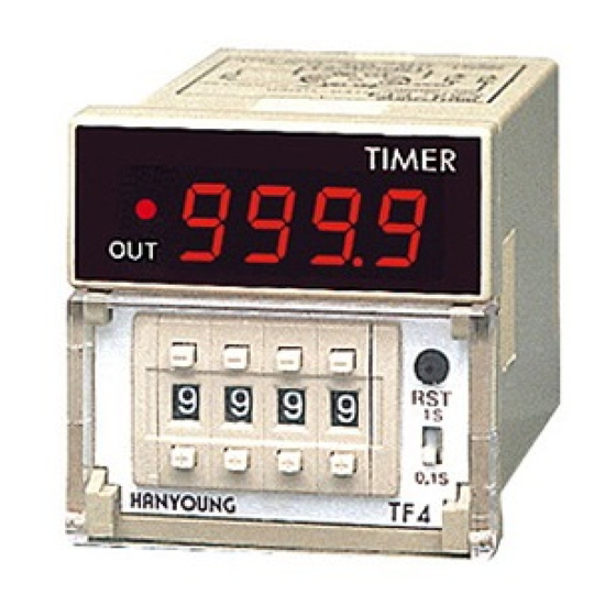
▍ Part names
Output Indicator
MD0306KE190925
▍ Dimension & Panel cutout
■ Dimension
■ Panel cutout
▍ Connection diagram
■ Contect control output
INHIBIT
RESET
INHIBIT
RESET
▍ Operation chart
■ Up display
Power
Power
Reset Input
Reset Input
Power Reset
Power Reset
Inhibit Input
Inhibit Input
Setting Value
Setting Value
Power
Digit Display
Digit Display
0
0
Control Output
Control Output
Out Display
Out Display
■ Output operation mode
0
Mode
Power Reset
Power Reset
Setting Value
Setting Value
Digit Display
Digit Display
0
0
Control Output
Control Output
N
Power Reset
Setting Value
Digit Display
0
1s
Time setting
switch
0.1s
1s
1m
999.9s / 9999s(A type)
9m 59.9s / 59m 59s(B type)
0.1s
0.1m
1s
0.1s
■ Contectless control coutput
INHIBIT
Power Supply
Power Supply
Power
Reset Input
Power Reset
■ Down display
Inhibit Input
Setting Value
Digit Display
TIME UP
0
TIME UP
Reset Input
Reset Input
Power Reset
Control Output
Power Reset
Inhibit Input
Inhibit Input
Setting Value
Setting Value
Out Display
Power
Digit Display
Digit Display
TIME UP
Reset Input
Power Reset
Control Output
Control Output
Inhibit Input
Out Display
Out Display
Setting Value
Digit Display
0
Control Output
Out Display
Power Reset
Setting Value
Power Reset
Power Reset
Digit Display
Setting Value
Setting Value
0
Digit Display
Digit Display
Control Output
Control Output
Control Output
Power Reset
Setting Value
Digit Display
0
Control Output
Operation after TIME-UP
Keep the output or display until the time when the reset is input.
Processing time
Manual reset
switch
0.1s/1s selection switch
999.9m / 59h 59m (C type)
[Unit:mm]
INHIBIT
RESET
RESET
Power Supply
Power Supply
TIME UP
Setting V
Power
Power
TIME UP
TIME UP
Control Ou
TIME UP
0
0
Up
0
0
Down
P
Reset
Power R
Inhibit
Digit Di
Out Di
Power
Setting
Digit D
Control O
Advertisement
Table of Contents

Related Manuals for HANYOUNG NUX TF4


Summary of Contents for HANYOUNG NUX TF4
- Page 1 Michuhol-gu, Incheon, Korea INSTRUCTION MANUAL TEL : +82-32-876-4697 Manual reset http://www.hynux.com switch Thank you for purchasing Hanyoung Nux products. Time setting Please read the instruction manual 0.1s/1s selection switch switch carefully before using this product, and use the product correctly.
- Page 2 • 전원 투입시에 접점출력의 준비 기간이 필요합니다. 외부의 인터록 ▍ 형명구성 회로 등에 신호로 사용되는 경우에는 지연 릴레이를 병용하여 주십시오. 형 명 코 드 내 용 TF4- □ □ □ □ 디지털 멀티타이머 (DIN 48 ㎜ × 48 ㎜) ▍ 접속도...
Need help?
Do you have a question about the TF4 and is the answer not in the manual?
Questions and answers